Rivet stringing apparatus and blind equipped with the same

a stringing apparatus and blind technology, applied in the field of blinds, can solve the problems of user hassle, failure to be fully deployed or collapsed, blinds to have asymmetrical heights, etc., and achieve the effect of stable deploymen

Inactive Publication Date: 2021-03-18
CHING FENG BLINDS INC CO LTD
View PDF0 Cites 1 Cited by
  • Summary
  • Abstract
  • Description
  • Claims
  • Application Information

AI Technical Summary

Benefits of technology

[0004]The primary objective of the present invention is to provide a stringing apparatus for a blind, and it is able to allow the lifting rope to be wound smoothly and flatly, thereby achieving the effect of stable deployment and collapsing of the blind sheet of a blind.
[0006]In view of the above, it can be understood that the stringing apparatus of the present invention utilizes the ratio relationship of height of the rope winder in order to allow the lifting rope to be stably and smoothly wound onto the winding wheel, such that no interference of tangling of ropes occurs among different loops of the rope, thereby achieving the effect of stable deployment and collapsing of the blind sheet of the blind.

Problems solved by technology

If such situation is severe, then the issue of unsmoothness or jamming of the lifting ropes 95 during the release or winding process thereof occurs, causing the blind to have asymmetrical heights on two sides, and the blind may even fail to be fully deployed or collapsed, causing hassles to users.

Method used


Image

  • Rivet stringing apparatus and blind equipped with the same
  • Rivet stringing apparatus and blind equipped with the same
  • Rivet stringing apparatus and blind equipped with the same

Examples


Embodiment Construction

[0018]The Applicant first emphasizes herein that in the entire specification, including embodiments and claims, terms related to directions shall be based on the direction illustrated in the drawings. In addition, in the embodiments and drawings disclosed in the following, identical or similar elements or features are identified by the same numbers throughout all figures.

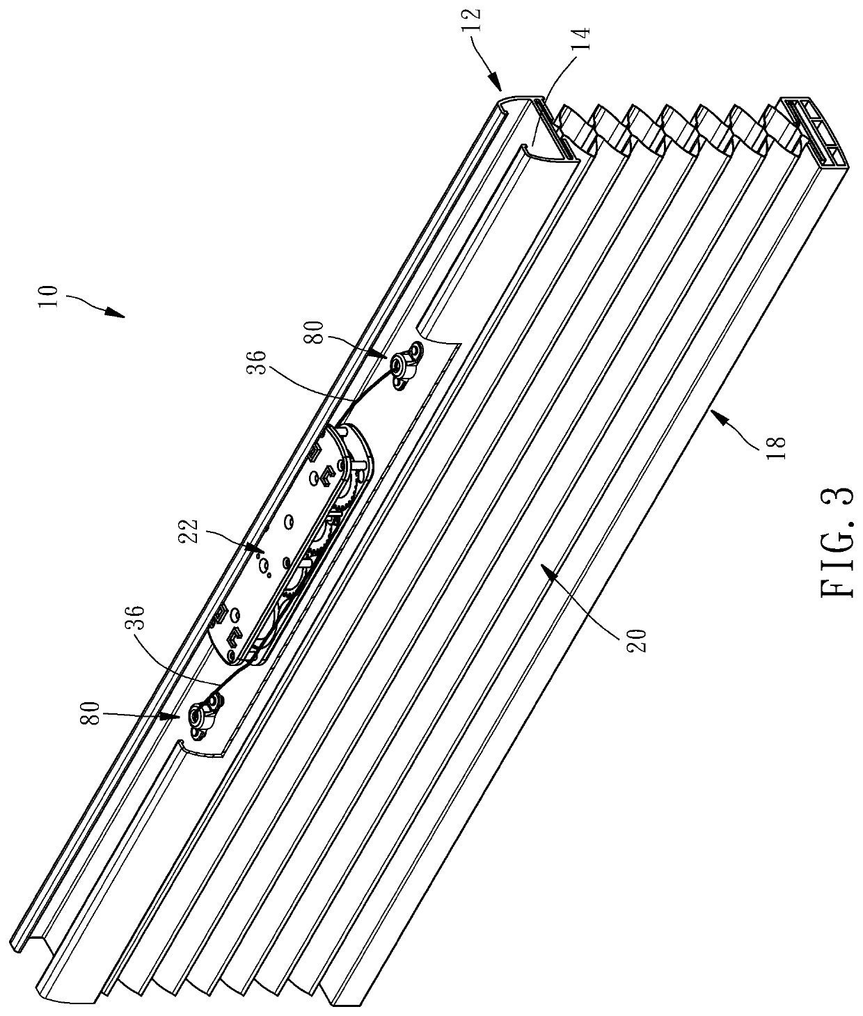
[0019]Please refer to FIG. 3 and FIG. 4. As shown in the drawings, a blind 10 comprises an upper beam 12, a lower beam 18, a blind sheet 20, a rope winder 22 and two lifting ropes 36.

[0020]The upper beam 12 includes a bottom wall 14, and the bottom wall 14 includes two through holes 16 penetrating through the two top and bottom surfaces thereof (as shown in FIG. 6A and FIG. 6B). In addition, two sides of any one through hole 16 of the bottom wall 14 includes two sets of holes 161 penetrating through the two top and bottom surfaces thereof.

[0021]The blind sheet 20 (a honeycomb blind is used as an example for illustra...


PUM


Abstract

The blind includes an upper beam, a rope winder and a lifting rope. The bottom wall of the upper beam includes a through hole for the lifting rope to penetrate therethrough. The rope winder is arranged inside the upper beam and includes a top plate and a bottom plate. A winding wheel for winding the lifting rope is arranged between the top and bottom plates. The stringing apparatus of the present invention is arranged on the bottom wall of the upper beam and protrudes out of the top surface of the bottom wall. The relationship between a vertical distance from the bottom surface of the top plate of the rope winder to the top surface of the rope winder and a distance from the top surface of the stringing apparatus to the top surface of the bottom wall of the upper beam satisfies the relation of 2-5:1.

Description

BACKGROUND OF THE INVENTION1. Technical Field[0001]The present invention relates to a blind, in particular, to a stringing apparatus for a blind and a blind equipped with such stringing apparatus.2. Description of Related Art[0002]In general, as shown in FIG. 1, a blind without the exposure of pulling strings mainly utilizes a rope winder 92 installed inside the upper beam 90 to perform rolling and releasing of the two lifting ropes 95 on the left and right sides thereof. Since one ends of the two left and right lifting ropes 95 are attached onto the lower beam, the lower beam is able to gradually ascend during the rolling process of the two left and right lifting ropes 95, in order to achieve the collapsing effect of the blind through the upward movement of the lower beam.[0003]Furthermore, the bottom wall 91 of the upper beam 90 is typically installed with a stringing apparatus 96 provided for the lifting ropes 95 for penetrating therethrough, such that the stringing apparatus 96 ...

Claims


Application Information

Patent Timeline
Patent Type & Authority Applications(United States)
IPC IPC(8): E06B9/322E06B9/327
CPCE06B9/322E06B9/327E06B9/323E06B2009/3222
Inventor LIANG, WEN-YING
Owner CHING FENG BLINDS INC CO LTD
Why Eureka
Try Eureka