Honing machine

Pending Publication Date: 2021-04-01
KADIA PRODN
View PDF11 Cites 4 Cited by
  • Summary
  • Abstract
  • Description
  • Claims
  • Application Information

AI Technical Summary

Problems solved by technology

The expansion drive and the rotary drive are subject to wear in particular in the region of the ball bearings, such that, after a few years of operation of the honing unit, it may be necessary for the rotary drive, the expansion drive, or both assemblies, to be overhauled.
This is an expenditure of time and requires a highly skilled technician.
Although the expansion drive, with further components of the expansion system,

Method used


Image

  • Honing machine
  • Honing machine
  • Honing machine

Examples


Embodiment Construction

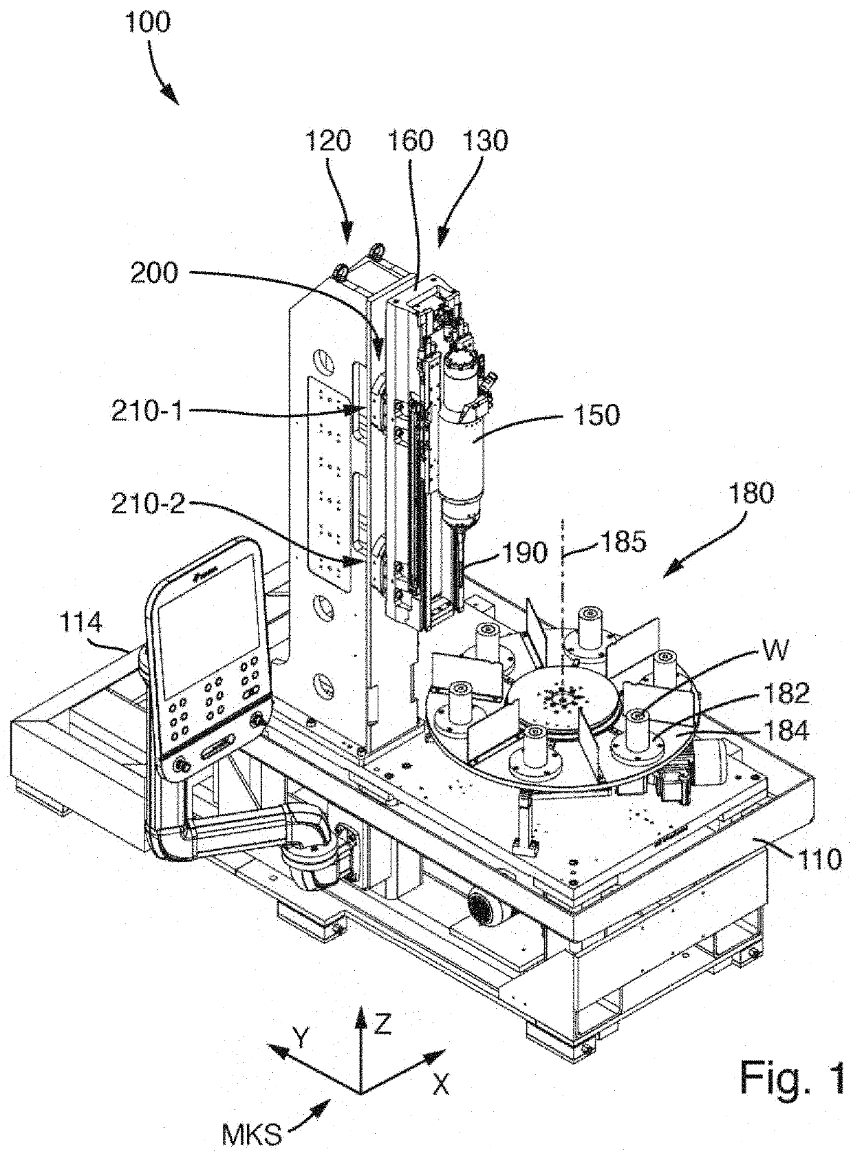
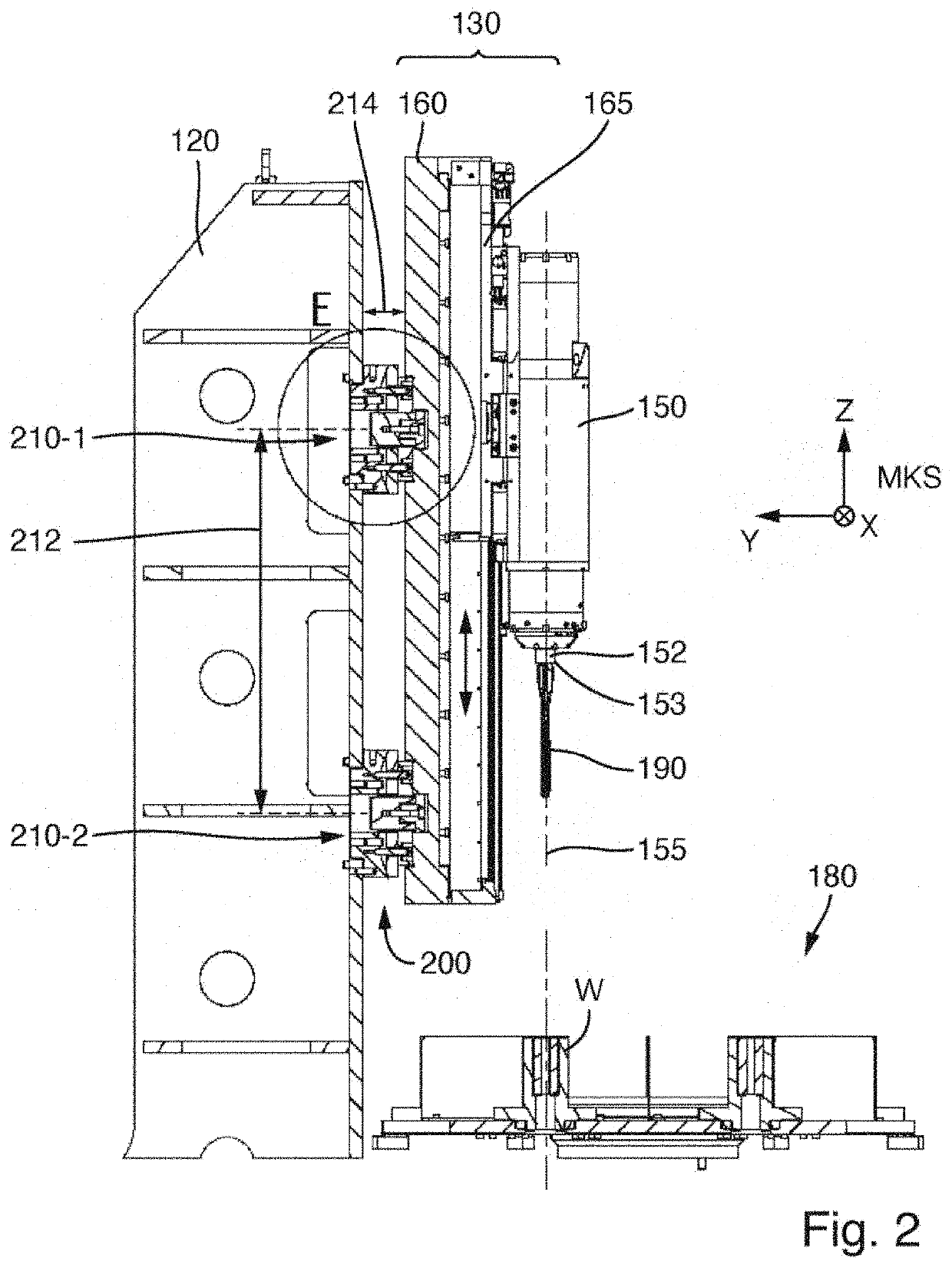
[0037]FIG. 1 shows an oblique perspective view of a honing machine 100 according to an exemplary embodiment. FIG. 2 shows a vertical section through a honing unit arranged on the support structure of the honing machine and components of a rotary table transport system. In the configuration shown, the honing machine has only a single honing unit. A second support structure with a second honing unit for machining the same workpieces may be provided.

[0038]The honing machine 100 has a substantially rectangular machine base 110 with a frame and a base plate which is or should be oriented horizontally in the case of a fully set-up honing machine. The rectangular base plate is somewhat longer in the first direction (longitudinal direction) running parallel to the y axis of the machine coordinate system MKS than in the second direction (transverse direction) which is perpendicular thereto and which runs parallel to the x axis of the machine coordinate system. Close to the rear side 114 of t...


PUM


Abstract

A honing machine for honing a bore in a workpiece comprises a support structure fixed to the machine and at least one honing unit which is mounted on the support structure and which has a spindle unit (150) in which a spindle shaft (152) is rotatably mounted, wherein the spindle shaft (152) is rotatable about a spindle axis (155) by means of a rotary drive (450) and, at a tool-side end (153), has a device for the fastening of an expandable honing tool. The honing machine furthermore comprises a stroke drive for generating a stroke movement of the spindle unit (150) and an expansion drive (550) for expanding the honing tool, wherein the expansion drive is coupled to an advancing rod (460) which runs in the interior of the spindle shaft. The spindle unit (150) has a spindle unit housing (310) which has a first housing portion (310-1) for accommodating the rotary drive (450) and a second housing portion (310-2) for accommodating the expansion drive (550). The rotary drive (450) is accommodated in an exchangeable first cartridge (400) and the expansion drive (550) is accommodated in a second cartridge (500) which is exchangeable independently of the first cartridge (400), wherein the first cartridge (400) is introducible into the first housing portion (310-1) and the second cartridge (500) is introducible into the second housing portion (310-2).

Description

FIELD OF APPLICATION AND PRIOR ART[0001]This application claims priority to German Patent Application DE 10 2019 214 873.5 filed Sep. 27, 2019, the entirety of which is incorporated herein by reference.[0002]The invention relates to a honing machine for honing a bore in a workpiece.[0003]Honing is a cutting machining method using geometrically undefined cutting edges, in the case of which a honing tool performs a cutting movement composed of two components and there is constant areal contact between one or more cutting material bodies, for example honing strips, of the honing tool and the bore inner surface to be machined. The kinematics of a honing tool are characterized by a superposition of a rotational movement and a stroke movement running in an axial direction of the bore. Normally, an optional expansion movement is also provided, which leads to a variation of the effective diameter of the honing tool.[0004]A one-off stroke movement of the honing tool within the bore, composed...

Claims


Application Information

Patent Timeline
IPC IPC(8): B24B33/02
CPCB24B33/027B24B33/02B24B33/10B24B55/02
Inventor MOOS, UWEREGLER, ROLAND
Owner KADIA PRODN
Why Eureka
Try Eureka