Process cartridge and image forming apparatus

Active Publication Date: 2021-04-22
SHARP KK
View PDF0 Cites 0 Cited by
  • Summary
  • Abstract
  • Description
  • Claims
  • Application Information

AI Technical Summary

Benefits of technology

[0030]A process cartridge and an image forming apparatus according to some aspects of the present invention enable detachment and attachment of a charge roller unit from and to a process cartridge without damage to

Problems solved by technology

However, it is assumed that, sometimes, the charge roller may inadvertently come into contact with the surface of the photosensitive drum and cause damage, or a lubricant or the like applied to the photosensitive drum may adhere to the surface of the charge roller and cause poor charging.
However, although Japanese Unexamined P

Method used


Image

  • Process cartridge and image forming apparatus
  • Process cartridge and image forming apparatus
  • Process cartridge and image forming apparatus

Examples


first embodiment

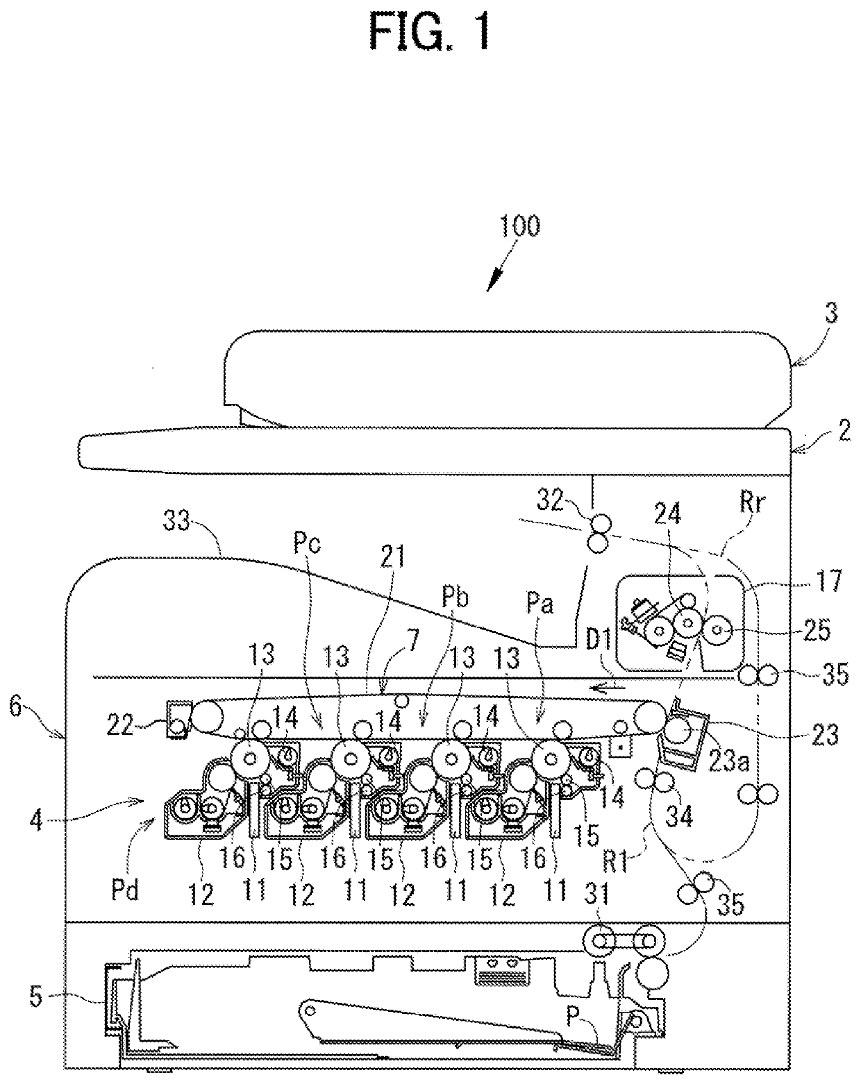
[0048]FIG. 1 is a cross-sectional view of the overall configuration of an image forming apparatus 100 including a process cartridge 200 according to the present embodiment, in view from the front.

[0049]The image forming apparatus 100 has a copying function of reading a document and printing the read document on a recording sheet. As illustrated in FIG. 1, the image forming apparatus 100 includes an image reading device 2, an automatic document feeder (ADF) 3, a printing unit 4, and a paper feed cassette 5. The printing unit 4 and the paper feed cassette 5 are built in a body 6 of the image forming apparatus 100. The image reading device 2 and the ADF 3 are mounted on the upper portion of the body 6.

[0050]The image data processed by the image forming apparatus 100 corresponds to a color image in the colors black (K), cyan (C), magenta (M), and yellow (Y) or a monochrome image in a single color (for example, black). Therefore, the printing unit 4 includes four image stations Pa, Pb, P...

second embodiment

[0090]The second embodiment differs from the first embodiment in that an operation portion 65A is provided that extends in the axial direction of the charge roller 15. In the following description, the same components as those in the first embodiment are denoted by the same reference numerals, and the description thereof will be omitted. Only the configurations different from the first embodiment will be described.

[0091]FIG. 10 is an enlarged perspective view of the right end portion of a charge roller unit 300A that is to be attached to a process cartridge 200A according to the second embodiment. As illustrated in FIG. 10, the operation portion 65A as well as the operation portion 65 are disposed on a support 60A (right support section 60aA and left support section 60bA) disposed at the left and right ends of a housing frame 50A.

[0092]The operation portion 65A extends in the axial direction of the charge roller 15 relative to a support body 61A. The operation portion 65A passes thr...

third embodiment

[0097]The third embodiment differs from the first embodiment in that it includes a retainer 80 that retains the charge roller 15 at the remote position PA1 and a releaser 90 that releases the retained state of the retainer 80. In the following description, the same components as those in the first embodiment are denoted by the same reference numerals, and the description thereof will be omitted. Only the configurations different from the first embodiment will be described.

[0098]FIGS. 11A, 11B, 12A, and 12B are cross-sectional views of a process cartridge 200B and a charge roller unit 300B according to the third embodiment in states in which the charge roller unit 300B is to be attached to the process cartridge 200B. As illustrated in FIG. 11A, the charge roller unit 300B includes a retainer 80. The retainer 80 retains the charge roller 15 at the remote position PA1. The retainer 80 has a latch 81 and a latched portion 83.

[0099]The latch 81 is disposed on a support 60B, and the latch...


PUM


Abstract

A process cartridge includes a photosensitive drum, a charge roller unit, and a storage recess. The photosensitive drum is disposed on a body frame. The charge roller unit includes a charge roller and is separate from the body frame. The storage recess stores the charge roller unit. The charge roller unit includes a storage frame and a support. The support supports the charge roller and is movably held on the storage frame. The support includes an operation portion that switches between a remote position and a contact position while the charge roller unit is stored in the storage recess. In the remote position, the charge roller is separated from the photosensitive drum. In the contact position, the charge roller is in contact with the photosensitive drum.

Description

BACKGROUND OF THE INVENTIONField of the Invention[0001]The present invention relates to a process cartridge including a charge roller and a photosensitive drum, and an image forming apparatus, more particularly to measures for improving maintenance workability, such as replacement of a charge roller.Description of the Background Art[0002]Conventionally, a process cartridge of an image forming apparatus includes a unit that integrates a charge roller and a photosensitive drum, to reduce the size of the process cartridge. The charge roller is often integrated with, for example, a charge cleaning roller, etc., into a charge roller unit.[0003]During maintenance of the process cartridge, such as replacement of the charge roller, the photosensitive drum is removed first, and then the charge roller unit is removed so that the photoconductive surface of the photosensitive drum is not damaged. When the replaced charge roller unit is installed, the charge roller unit is installed first, and t...

Claims


Application Information

Patent Timeline
IPC IPC(8): G03G21/18G03G15/02
CPCG03G21/1814G03G15/0216
Inventor YOSHIMOTO, YUHSUKE
Owner SHARP KK
Why Eureka
Try Eureka