Helical reinforcement wheel welding and forming equipment and forming method thereof

A technology of spiral steel bar and rotating device, applied in welding power source, welding equipment, resistance welding equipment and other directions, can solve the problems of inefficient, multi-manpower and time, consumption and so on

Inactive Publication Date: 2010-05-26
YONGJU IND
View PDF6 Cites 0 Cited by
  • Summary
  • Abstract
  • Description
  • Claims
  • Application Information

AI Technical Summary

Problems solved by technology

In the design structure that uses spiral steel bars as the main body of the skeleton, it will further use manpower binding or spot welding to set point bars on the sides of the spiral steel bars to form a spiral steel bar cage. In addition to consuming more manpower and time, In the case of increasing demand for the use of spiral steel bars, it is also less cost-effective

Method used


Image

  • Helical reinforcement wheel welding and forming equipment and forming method thereof
  • Helical reinforcement wheel welding and forming equipment and forming method thereof
  • Helical reinforcement wheel welding and forming equipment and forming method thereof

Examples


Embodiment Construction

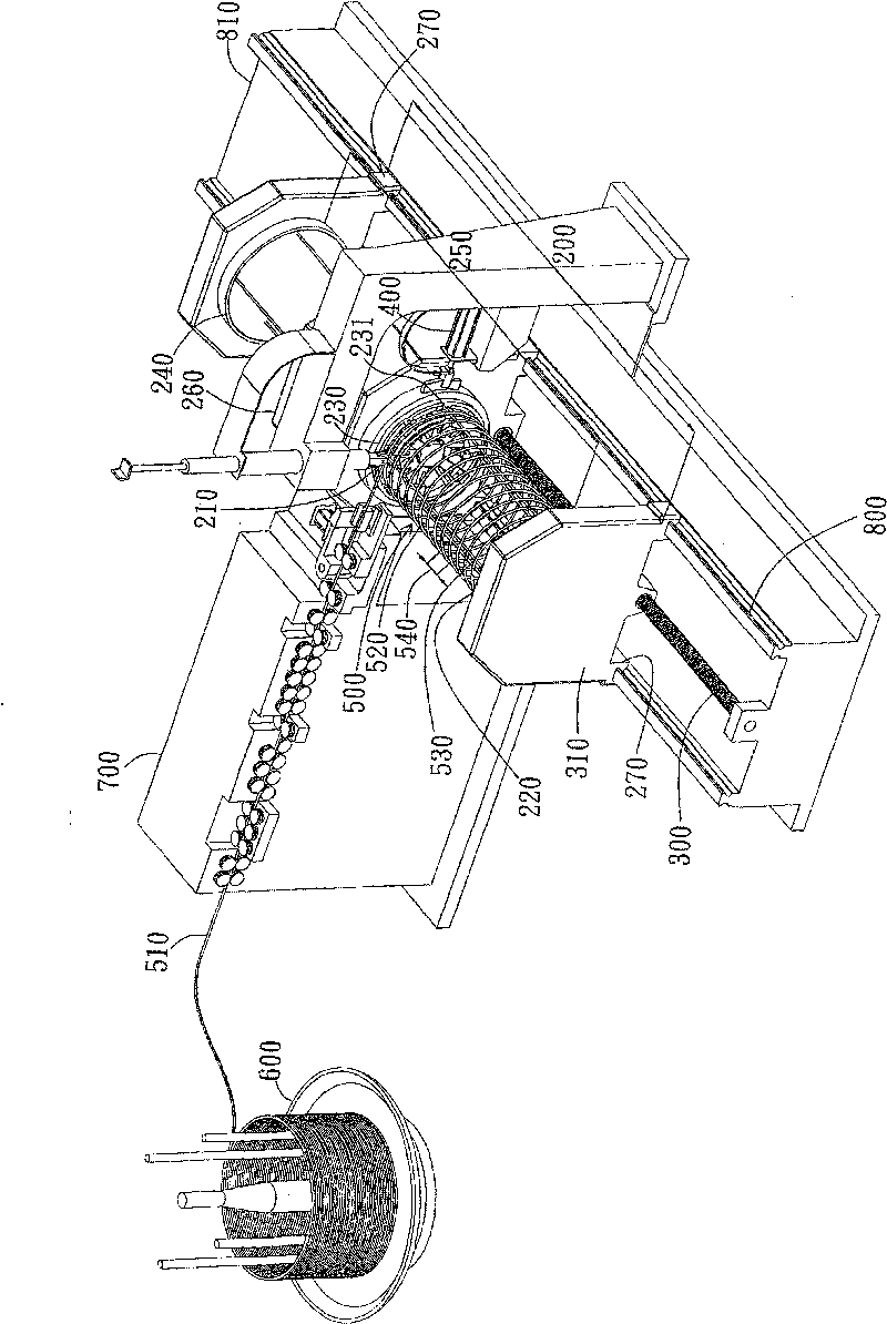
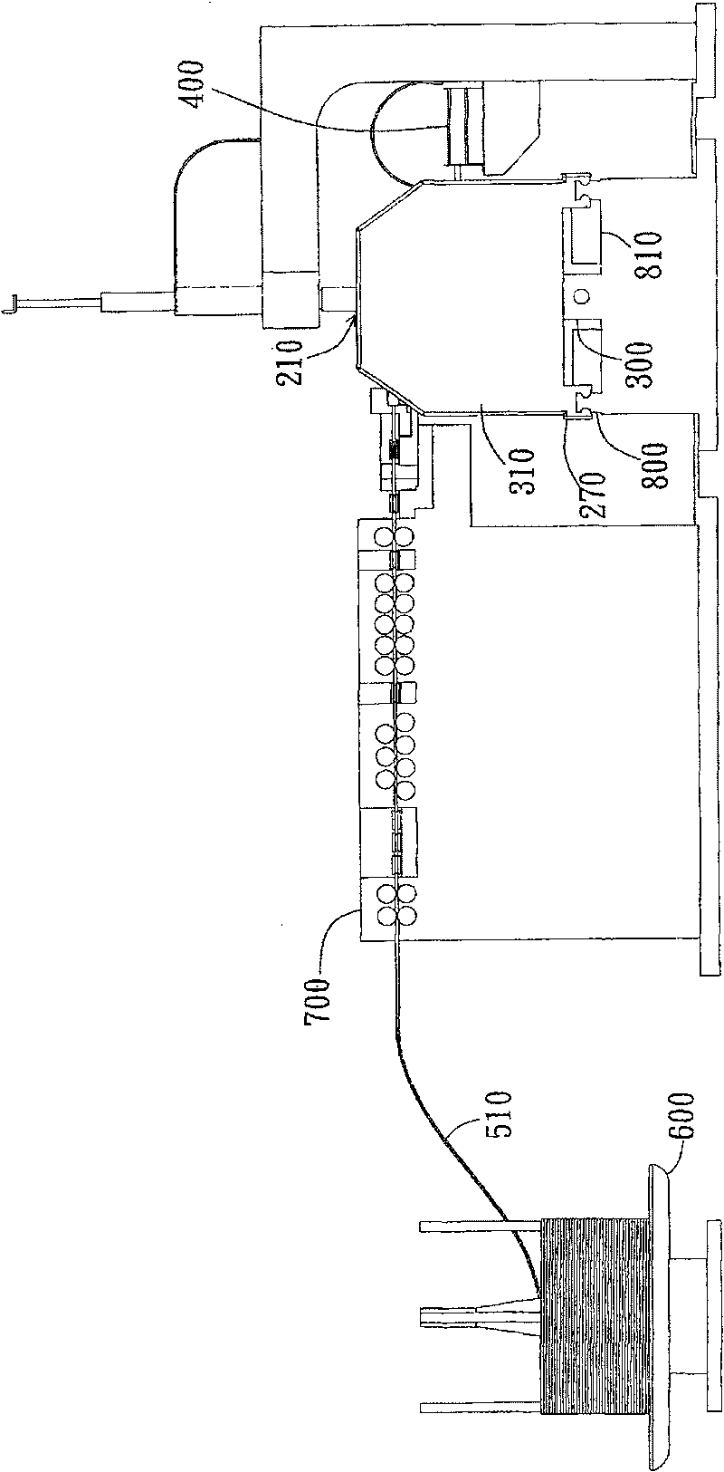
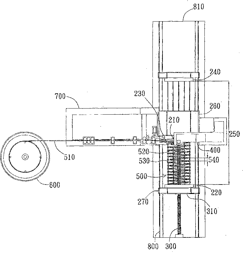
[0058] The invention provides a spiral steel bar wheel welding forming device for efficiently forming a spiral steel bar cage. The spiral steel bar wheel welding forming device of the present invention is preferably used to replace the previous construction method of manually binding spot bars and spiral steel bars with iron wires or spot welding. The spiral steel cage formed by the spiral steel bar wheel welding forming device of the present invention is preferably used for reinforced concrete cylinders in construction industry, construction industry, traffic road engineering, aquatic product engineering and the like. However, in different embodiments, the shaped helical reinforcement cage can also be used as a stirrup structure of a building or other structural units of a building.

[0059] Such as figure 1 As shown, the spiral steel bar wheel welding forming device of the present invention is preferably used to form a spiral steel bar cage 500 with a plurality of pitches 5...


PUM


Abstract

The invention relates to a wheel welding forming device of spiral steel bars and a forming method thereof. The spiral steel bar wheel welding forming device comprises a material-placing rotation device, a pushing device and a wheel welding device. The material-placing rotation device comprises a bar-entering side, a first rotation part and a wheel-shaped self-rotation part. The wheel-shaped self rotation part is provided with a plurality of point bar pores annularly arranged, and the pores are used for the point bars to push against the fist rotation part to form a wheel welding unit after passing the pores; the pushing device is connected with the first rotation part in the way of being capable of moving along an axial direction; the wheel welding device is arranged at the side of the wheel-shaped self-rotation part, corresponding to the point bar pores. When the steel bars are extended into the material-placing rotation device from the bar-entering side, the wheel-shaped self-rotation part rolls the steel bars to be round to form hoop bars encircling the wheel welding unit; and the wheel welding device is matched with the displacement movement of the pushing device along the axial direction and welds the hoop bars and the point bars one by one to form a spiral steel bar cage.

Description

technical field [0001] The present invention relates to a spiral steel bar wheel welding forming device and its forming method; specifically, the present invention relates to a steel cage automatic production machine for efficiently forming a spiral steel cage. Background technique [0002] With the improvement of structural strength requirements for various buildings, the design strength provided by the skeleton composed of spiral steel bars has been paid attention to by the structural design of the engineering field. The so-called spiral stirrup refers to the spiral steel bar bent into a continuous spiral as the stirrup matched with the main reinforcement, which has the effect of fixing the position of the main reinforcement and providing shear strength. The cross-sectional shape of the spiral steel bar can be adjusted according to the actual design, and the more common ones are circular and rectangular. In addition to being widely used as stirrups in beam-column structur...

Claims


Application Information

Patent Timeline
Patent Type & Authority Patents(China)
IPC IPC(8): B23P23/04B21F3/02B21F15/08B21F1/02B23K11/11B23K11/26B23P15/00E04C5/01
CPCB21F27/124
Inventor 尹衍樑
Owner YONGJU IND
Why Eureka
Try Eureka