Mobil c-arm x-ray imaging system

Inactive Publication Date: 2021-05-13
KONINKLJIJKE PHILIPS NV
View PDF0 Cites 0 Cited by
  • Summary
  • Abstract
  • Description
  • Claims
  • Application Information

AI Technical Summary

Benefits of technology

The technical effects of this patent text are to provide an improved and easy way to position a mobile C-arm system.

Problems solved by technology

Mobile C-arm X-ray imaging systems can be relatively bulky and correct positioning may be difficult.
However, it has been shown that due to increasing demands for a precise positioning, the positioning of a C-arm of mobile X-ray systems can be cumbersome.

Method used


Image

  • Mobil c-arm x-ray imaging system
  • Mobil c-arm x-ray imaging system

Examples


Embodiment Construction

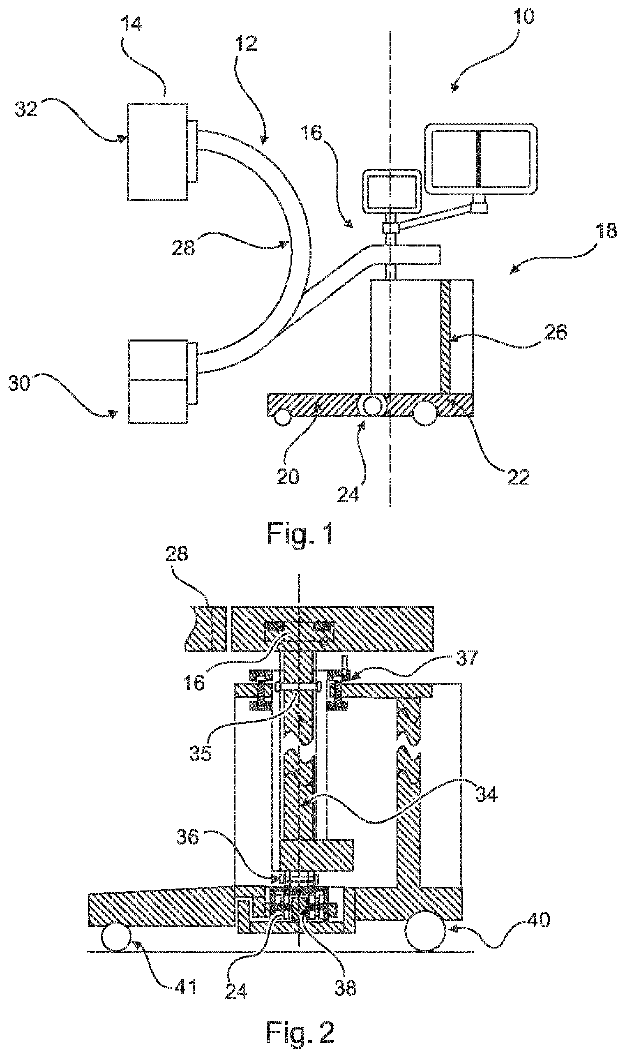
[0048]FIG. 1 illustrates a mobile C-arm X-ray imaging system 10 comprising a C-arm imaging assembly 12 with a C-arm device 14. Further, the C-arm imaging assembly comprises a mobile stand assembly 18 comprising a first base 20 and a second base 22. The C-arm assembly is coupled to the mobile stand assembly allowing a horizontal pivoting movement of the C-arm device. One of the first and second base is pivotable in a horizontal plane.

[0049]In an example, one of the first and second base is coupled to the second base such that the first base follows the horizontal pivoting movement of the C-arm device.

[0050]In an example, the C-arm device is coupled to the mobile stand assembly via a C-arm bearing arrangement 16 allowing a horizontal pivoting movement.

[0051]In an example, the first base 20 is coupled to the second base 22 via a base support (or bearing) arrangement 24.

[0052]In an example, the second base is temporarily stationary and the first base 20 is pivotable in relation to the s...


PUM


Abstract

The present invention relates to mobile C-arm X-ray imaging. In order to provide an improved and facilitated positioning of a mobile C-arm system, a mobile C-arm X-ray imaging system (10) is provided comprising a C-arm imaging assembly (12) with a C-arm device (14), and a mobile stand assembly (18) comprising a first base (20), and a second base (22). The C-arm imaging assembly is coupled to the mobile stand assembly allowing a horizontal pivoting movement of the C-arm device. One of the first base and second base is pivotable in a horizontal plane.

Description

FIELD OF THE INVENTION[0001]The present invention relates to a mobile C-arm X-ray imaging system and a corresponding method for adjusting a position of a mobile C-arm imaging device.BACKGROUND OF THE INVENTION[0002]Mobile C-arm X-ray imaging systems are used, for example, during invasive surgical procedure, examination procedures and the like. Mobile C-arm X-ray imaging systems can be relatively bulky and correct positioning may be difficult. Positioning of the C-arm in relation to the patient may necessitate rotating the entire mobile X-ray system. US 2012 0219122 A1 relates to a wheeled C-arm support device for a mobile C-arm X-ray machine. The C-arm support device includes two steerable front wheels, two freely movable rear wheels and a steering unit. However, it has been shown that due to increasing demands for a precise positioning, the positioning of a C-arm of mobile X-ray systems can be cumbersome.SUMMARY OF THE INVENTION[0003]There may thus be a need to provide an improved ...

Claims


Application Information

Patent Timeline
IPC IPC(8): A61B6/00
CPCA61B6/4441A61B6/4405
Inventor MUNGASE, GANESH CHANDRAKANT
Owner KONINKLJIJKE PHILIPS NV
Why Eureka
Try Eureka