Thrust reverser having aerodynamic coupling for front frame

A technology of thrust reversal and front frame, applied in the direction of jet propulsion devices, machines/engines, etc., can solve problems such as reducing the efficiency of thrust reversal equipment, and achieve the effect of optimized positioning

Inactive Publication Date: 2013-03-06
AIRCELLE
View PDF8 Cites 2 Cited by
  • Summary
  • Abstract
  • Description
  • Claims
  • Application Information

AI Technical Summary

Problems solved by technology

[0025] However this solution is practically limited: in thrust reversal mode, the airflow tends to follow its direct path instead of reattaching to the deflecting edge, which drastically reduces the efficiency of the thrust reversal device

Method used


Image

  • Thrust reverser having aerodynamic coupling for front frame
  • Thrust reverser having aerodynamic coupling for front frame
  • Thrust reverser having aerodynamic coupling for front frame

Examples


Embodiment Construction

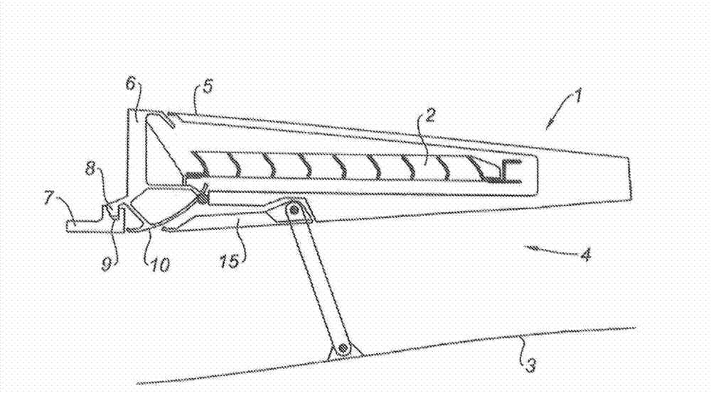
[0049] figure 1 A thrust reversal device 1 with a deflection grid 2 is schematically shown in longitudinal section.

[0050] This thrust reversal device 1 is equipped with a rear section surrounding the nacelle of the turbojet engine (not shown) and together with a fixed internal fixed fairing 3 at the rear of the turbojet engine defines the so-called The flow path 4 through which the second air flow flows.

[0051] Said thrust reversal device 1 comprises a movable cowl 5 mounted so as to be able to move in translation along the substantially longitudinal axis of the nacelle between an open position and a closed position in which said movable cowl 5 has The reverse movement replaces the passage in the nacelle and exposes the deflection grille 2 , said movable cowl 5 ensuring the continuity of the nacelle and covering said deflection grille 2 in the closed position.

[0052] The movable hood 5 is movable relative to a fixed structure comprising on the one hand support and gui...


PUM


Abstract

The present invention relates to a thrust reverser (1) for a turbojet engine nacelle, including deflection means (2) combined with at least one movable cowl (5) mounted on at least one front frame (6) provided with means (8, 9) for connecting to a corresponding upstream portion (7), said movable cowl (5) being mounted so as to be movable between a closed position, in which it closes the nacelle and deactivates the deflection means, and an open position, in which it opens a passage and activates the deflection means, the thrust reverser being characterized in that the front frame has an upstream extension forming a deformable flap (111, 112) intended to aerodynamically interface with the upstream portion, and in that a portion of the movable cowl (15, 18) is shaped so as to interface, in the closed position, with said upstream attachment portion by forcing back the deformable flap.

Description

technical field [0001] The invention relates to a turbojet engine nacelle, the downstream section of which is equipped with thrust reversal equipment mounted on the front frame. Background technique [0002] The aircraft is driven by a plurality of turbojet engines housed in a nacelle which also houses components of auxiliary drive equipment related to its operation (such as a thrust reversal system) which provide multiple function. [0003] The nacelle usually has a tubular structure comprising an air intake upstream of the turbojet engine, an intermediate section surrounding the turbojet fan, and a downstream section surrounding the turbojet combustion chamber and accommodating thrust reversers if necessary, the nacelle usually terminating in As for the exhaust nozzle, the outlet of the nozzle is located downstream of the turbojet engine. [0004] Modern engines are designed to accommodate a twin-flow turbojet engine capable of generating, through the rotation of the fan...

Claims


Application Information

Patent Timeline
IPC IPC(8): F02K1/72
CPCF02K1/72F02K1/62F02K1/805
Inventor 居·伯纳德·沃琪尔让-菲利普·若勒
Owner AIRCELLE
Why Eureka
Try Eureka