
Braking device for driving shaft

Active Publication Date: 2021-05-27
RAINBOW SRL
View PDF0 Cites 0 Cited by
  • Summary
  • Abstract
  • Description
  • Claims
  • Application Information

AI Technical Summary

Benefits of technology

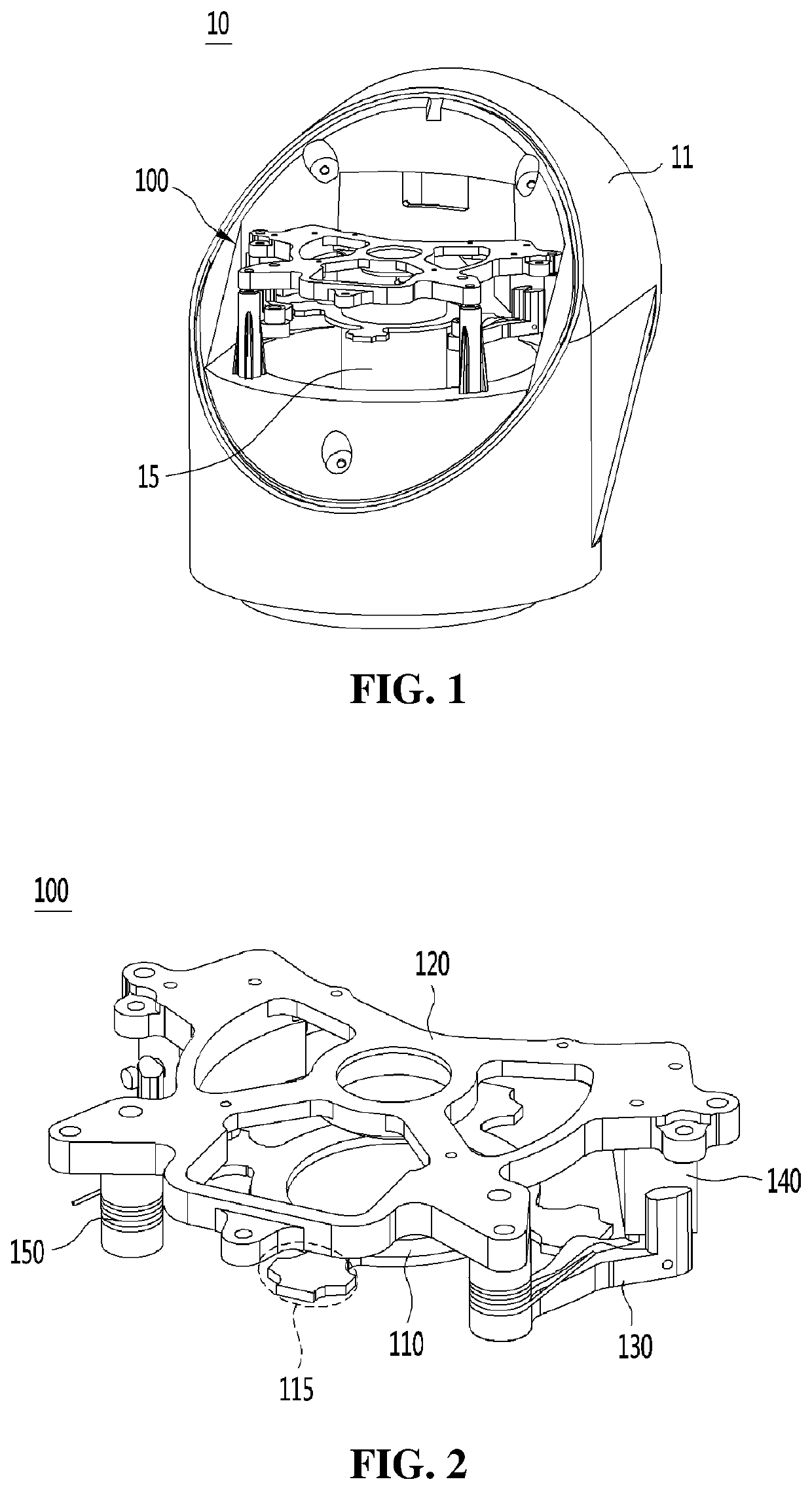
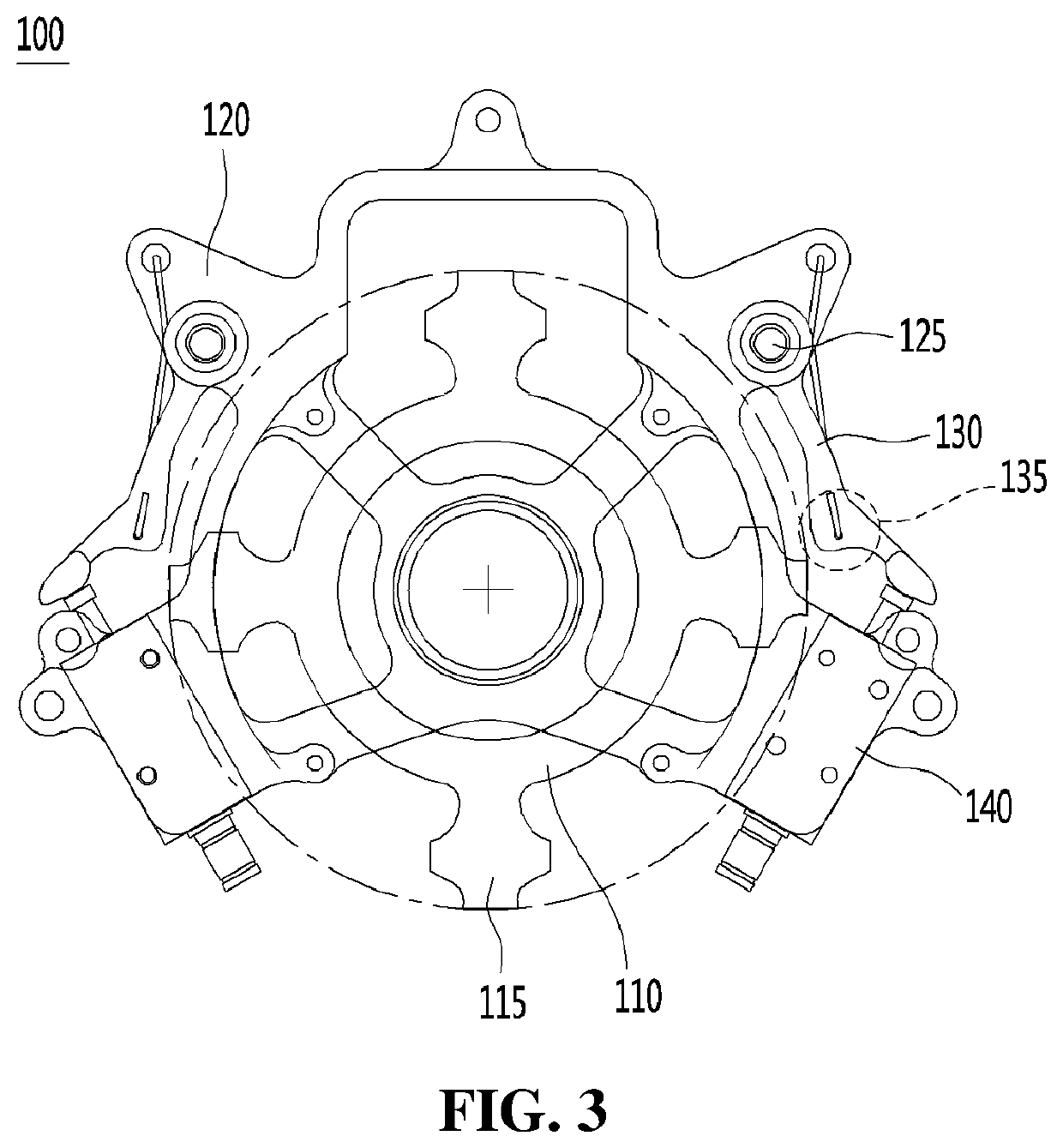
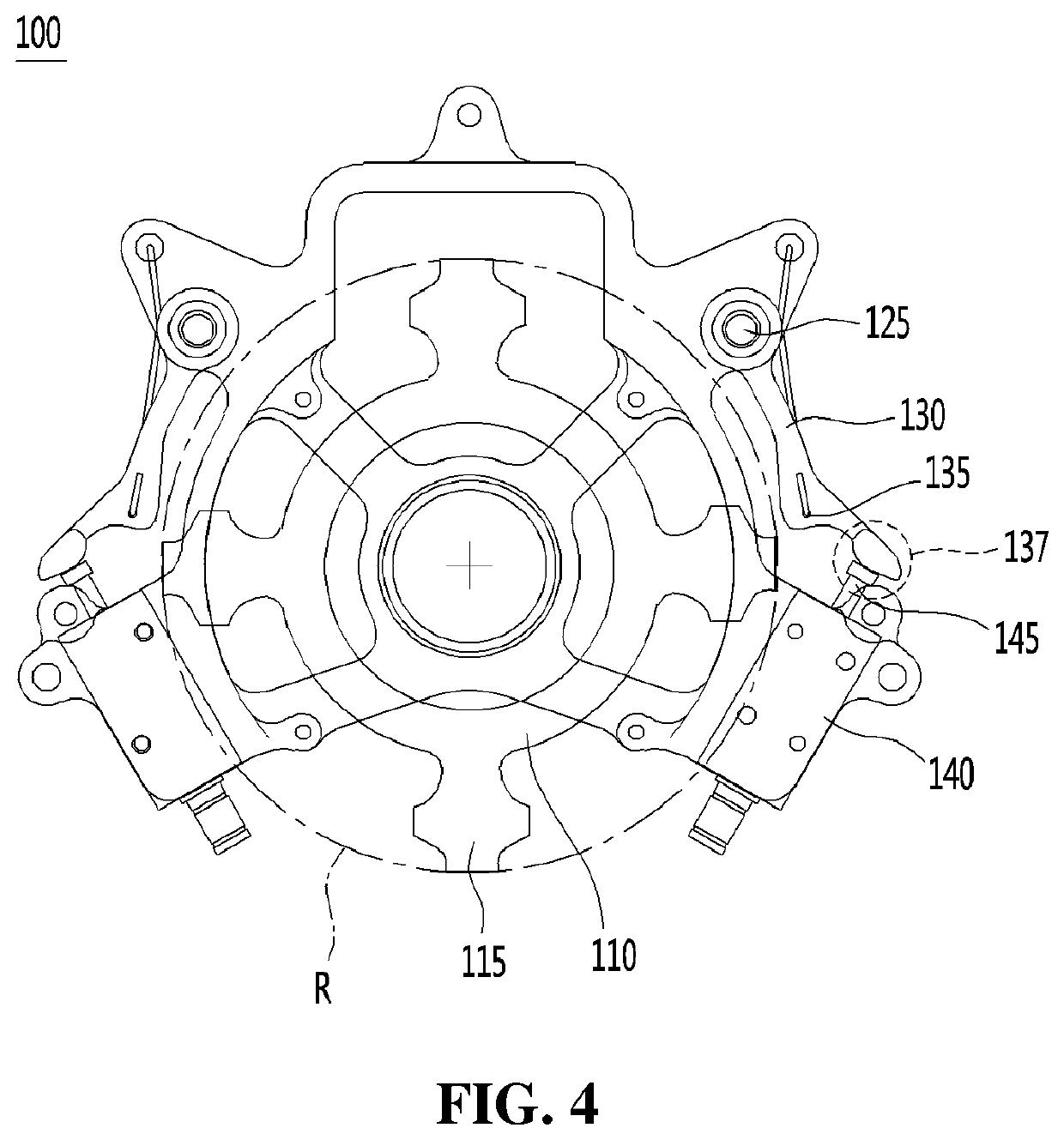
This patent describes a braking device for a robot that can stop its movement quickly and easily. The device consists of a brake ring and brake wings that are attached to the robot's frame. When the brakes are pressed, the brake ring stops rotating, and the brake wings spin around the brake shafts, causing them to lock into place. This stops the robot from moving. This braking device is effective even with small gaps between the brakes and can be used in both directions.

Problems solved by technology

In case of the conventional frictional type braking device, however, slip occurs during the braking operation, and accordingly, the conventional braking device cannot be used for a part where a stopping force is regulated in a relatively accurate manner, for example, for a robot articulation.

Method used


Image

  • Braking device for driving shaft
  • Braking device for driving shaft
  • Braking device for driving shaft

Examples


Embodiment Construction

[0020]While this invention is illustrated and described in a preferred embodiment, the device may be produced in many different configurations, forms, and materials. There is depicted in the drawings, and will hereinafter be described in detail, a preferred embodiment of the invention, with the understanding that the present disclosure is to be considered as an exemplification of the principles of the invention and the associated functional specifications for its construction and is not intended to limit the invention to the embodiment illustrated. Those skilled in the art will envision many other possible variations within the scope of the present invention.

[0021]It should be understood that detailed explanations on the principle, view and embodiment of the present invention may include structural and functional equivalents thereof. Further, it should be appreciated that such equivalents may include currently known equivalents as well as equivalents to be developed in the future, t...


PUM


Abstract

Provided is a braking device for a driving shaft, and the braking device includes: a brake ring coupled to the driving shaft in such a manner as to rotate according to rotation of the driving shaft and having one or more locking pieces with cross-shaped ends; a support frame fixed to an interior of a robot articulation; brake wings rotatable around brake shafts formed on the support frame and having locking protrusions adapted to stop the rotation of the driving shaft through physical interference with the cross-shaped ends of the locking pieces of the brake ring; position regulators adapted to rotate the brake wings to allow positions of the locking protrusions to be moved; and elastic members adapted to apply elastic forces to the brake wings rotating.

Description

TECHNICAL FIELD[0001]The present invention relates to a braking device for a driving shaft, which is used for a robot articulation and the like.BACKGROUND ART[0002]With the development of robot technologies, recently, needs for intelligent robots capable of performing various work as well as for robots for industrial uses, instead of human beings, have increasingly emerged, and accordingly, many studies on the intelligent robots are made.[0003]So as to develop the intelligent robots, advanced technologies like advanced materials, semiconductors, artificial intelligence, sensor software, and so on as well as traditional technologies like machines, electronics and so on are required, and unlike existing robots for industrial uses, the intelligent robots have the functions and performance necessary in future markets.[0004]On the other hand, the robots for industrial and service uses have been developed and used in various fields, and they perform high-skilled work as well as simple wor...

Claims


Application Information

Patent Timeline
IPC IPC(8): F16D63/00F16D65/16B25J9/10
CPCF16D63/006F16D2121/20B25J9/10F16D65/16F16D2121/22F16D2127/06B25J19/0004B25J9/12
Inventor LEE, JUNG HOHEO, JUNG WOOLIM, JEONG SOO
Owner RAINBOW SRL
Learn More