Mobile robot platform

Inactive Publication Date: 2008-03-25
VECNA
View PDF17 Cites 137 Cited by
  • Summary
  • Abstract
  • Description
  • Claims
  • Application Information

AI Technical Summary

Benefits of technology

[0030]Consequently, there exists a clear need for mobile apparatus that are better suited to higher agility on rugged terrain while engaged in a sequence of actions that involves at least lifting of cumbersome and heavy objects while achieving high mobility and high agility on rugged and otherwise steep or uneven terrain. The preferred em

Problems solved by technology

Robots are often used to perform tasks that are inherently dangerous for humans.
Robots are further used to lift and move objects which would be prohibitive or difficult to handle.
The known prior art presented provide publicly known solutions that advanced or now serve to advance the state of the art in mobile robotic platforms, but each known solution has readily observed problems or limitations.
This platform is, in effect, a derivative of WON and suffers from the same limitations of WON.
Although the device is comprised of an entirely wheeled mobility system, no other advantage is afforded the structure other than faster operation on normal terrain.
So, both these robots suffer from a common drawback.
First, they are limited to being configured with solely tracks or solely wheels, thereby limiting the number of end uses the platform may serve.
For these robots, having to carry such other forms of payloads can significantly complicate and fundamentally compromise their maneuverability and overall effectiveness.
It is a limitation of Chen that the relationship of the wheel set and track set in a particular leg are at a fixed angular position, one with respect to the other, and rotate in unison when deployed for the Chen maneuvers.
It is further noted that a limitation of Chen is that the payload must be placed on the mobile platform and conveyance is then elected as the next maneuver.
Chen therefore has the limitation of not being able to both lift and convey

Method used


Image

  • Mobile robot platform
  • Mobile robot platform
  • Mobile robot platform

Examples


Embodiment Construction

[0102]Embodiments of the present invention will be described below with reference to the accompanying drawings. It should be understood that the following description is intended to describe exemplary embodiments of the invention, and not to limit the invention.

[0103]It is understood that the present invention is not limited to the particular system components, analysis techniques, etc. described herein, as these may vary. It is also to be understood that the terminology used herein is used for the purpose of describing particular embodiments only, and is not intended to limit the scope of the present invention. It must be noted that as used herein and in the appended embodiments, the singular forms “a,”“an,” and “the” include plural reference unless the context clearly dictates otherwise.

[0104]Unless defined otherwise, all technical and scientific terms used herein have the same meanings as commonly understood by one of ordinary skill in the art to which this invention belongs. Pre...


PUM


Abstract

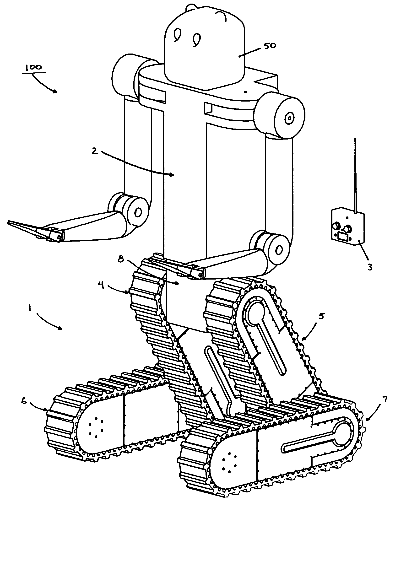
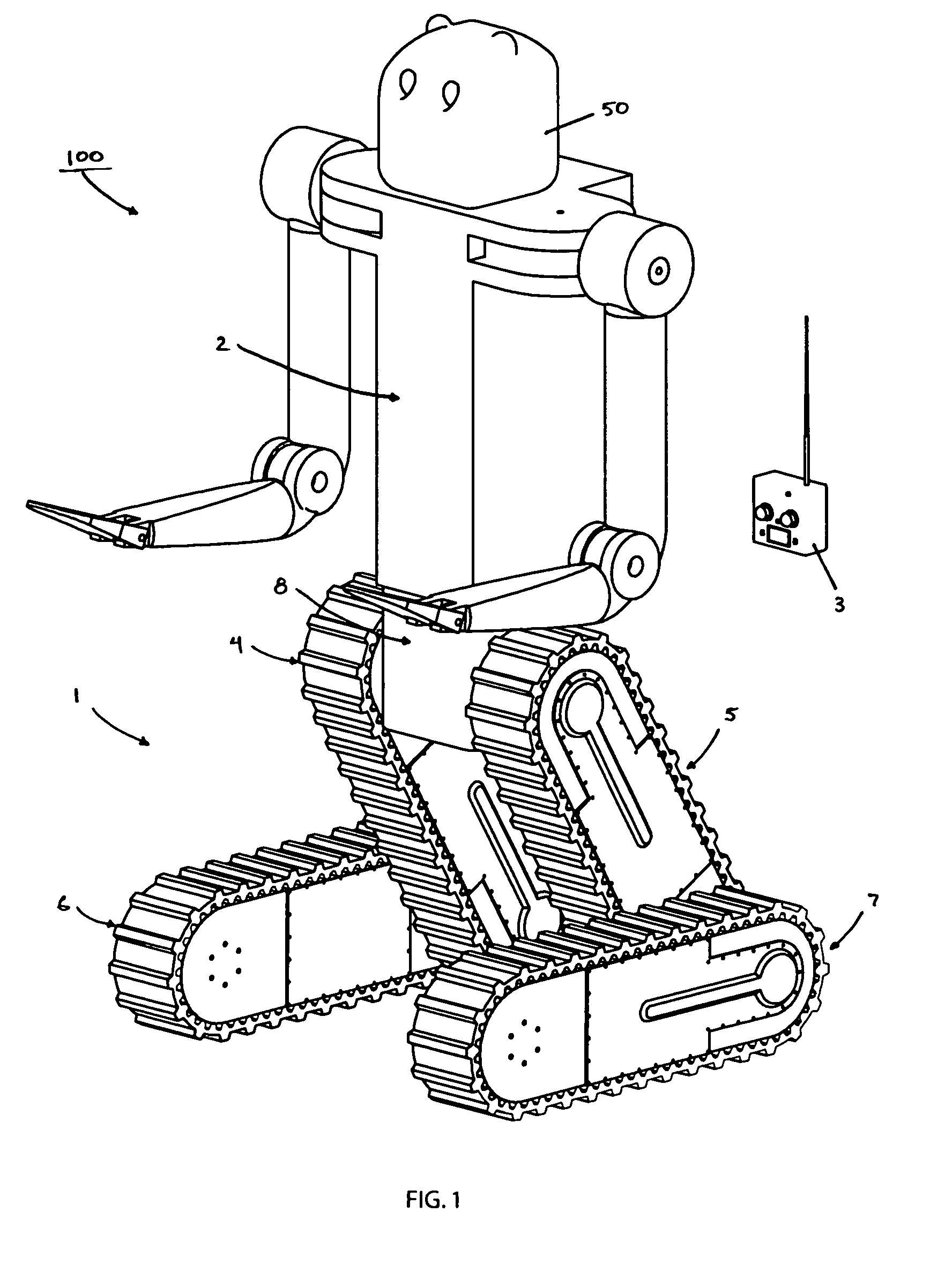
A mobile articulated robot platform is provided where the platform comprises a payload base hip section for attaching a torso, the platform having two opposing sides, where the platform includes a right leg assembly and a left leg assembly, with each leg assembly having an upper leg and a lower leg section, where the right and left leg assemblies each comprise a right upper leg being pivotally coupled on one side of said payload base hip section and a left upper leg being pivotally coupled to the other side of the payload base hip section, and a right lower leg being independently and pivotally connected to the right upper leg, and a left lower leg being independently and pivotally connected to the left upper leg, allowing rotation of each of the lower legs about each of the upper legs.

Description

BACKGROUND OF THE INVENTION[0001]The present invention relates generally to the field of mobile robots and in particular to articulated robot platforms comprising payload mounting assemblies, leg mounting assemblies and joints for combining leg assemblies, mobility elements for leg mounting assemblies including wheels, tracks, wheels and tracks, and to payload torsos in general including payload torsos with arms for lifting and extraction.[0002]The invention relates to robotic configurations which assume humanoid forms where there is a head, torso, hips, and legs. The present invention further relates to drive systems for driving tracks and wheels and to drive systems for rotationally moving leg assemblies at their joints. The present invention further relates to drive elements and control systems for establishing dynamic stability for such an articulated robot in various postures.[0003]Robots are often used to perform tasks that are inherently dangerous for humans. For example, rob...

Claims


Application Information

Patent Timeline
IPC IPC(8): B25J15/02
CPCB25J5/005B62D55/065B62D55/075B62D57/024B62D57/032
Inventor THEOBOLD, DANIELORNSTEIN, JOSHUANICHOL, JAMIE GKULLBERG, SCOTT ERIC
Owner VECNA
Why Eureka
Try Eureka