Proprotor blade with leading edge slot

a technology of propulsion blade and leading edge, which is applied in the direction of rotors, marine propulsion, vessel construction, etc., can solve the problems of affecting the performance of airplane mode, presenting many unique challenges, and tightening the size and length of propulsion blades, so as to increase the maximum lift, and increase the maximum lift

Inactive Publication Date: 2009-09-29
TEXTRON INNOVATIONS
View PDF17 Cites 20 Cited by
  • Summary
  • Abstract
  • Description
  • Claims
  • Application Information

AI Technical Summary

Benefits of technology

[0006]There is a need for a proprotor for tiltrotor aircraft and other rotorcraft that can provide improved hover maximum thrust capability without compromising the forward flight performance of the aircraft.
[0007]Therefore, it is an object of the present invention to provide a proprotor for a tiltrotor aircraft or other rotorcraft for which hover maximum thrust capability is increased without compromising the forward flight performance of the aircraft.
[0009]The proprotor blade with leading edge slot according to the present invention provides the following advantages: (1) significant maximum lift increments can be achieved without a significant increase in drag at low lift coefficients; (2) increases in maximum lift can be used to provide increases in maneuverability and agility, and / or increases in maximum payload; (3) 2-D dynamic stall vortex formation can be delayed to extremely high angles of attack; (4) pitching moment excursions caused by dynamic stall can be eliminated; (5) maximum lift-to-drag ratio capability is increased; (6) the slot is isolated from centrifugal force loads; (7) the blade spar can maintain a continuous load path; (8) aircraft vibration is reduced;.and (9) the slat can be easily removed in the field for repair or replacement without removing the entire proprotor blade.

Problems solved by technology

Although tilt rotor aircraft provide many unique advantages, they also present many unique challenges.
One problem is that the size and length of proprotors are tightly constrained.
Another problem in designing proprotors for tiltrotor aircraft is that changes that might increase performance in the helicopter mode, may adversely affect performance in the airplane mode, and vice versa.
For example, a change that is known to improve hover thrust in the helicopter mode may create a significant drag penalty in the airplane mode.
Although great strides have been made in the area of rotorcraft design, significant challenges remain.

Method used


Image

  • Proprotor blade with leading edge slot
  • Proprotor blade with leading edge slot
  • Proprotor blade with leading edge slot

Examples


Embodiment Construction

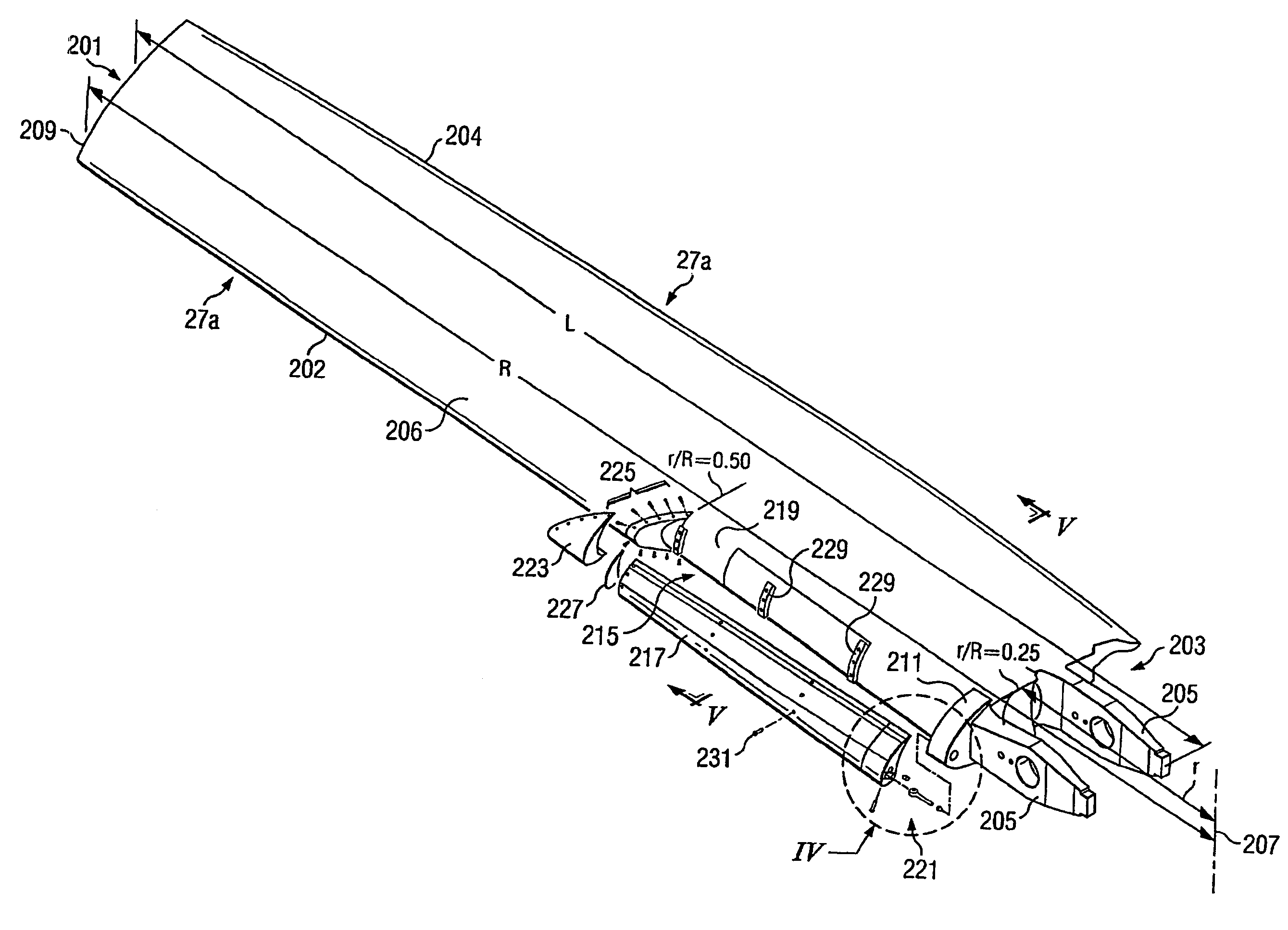
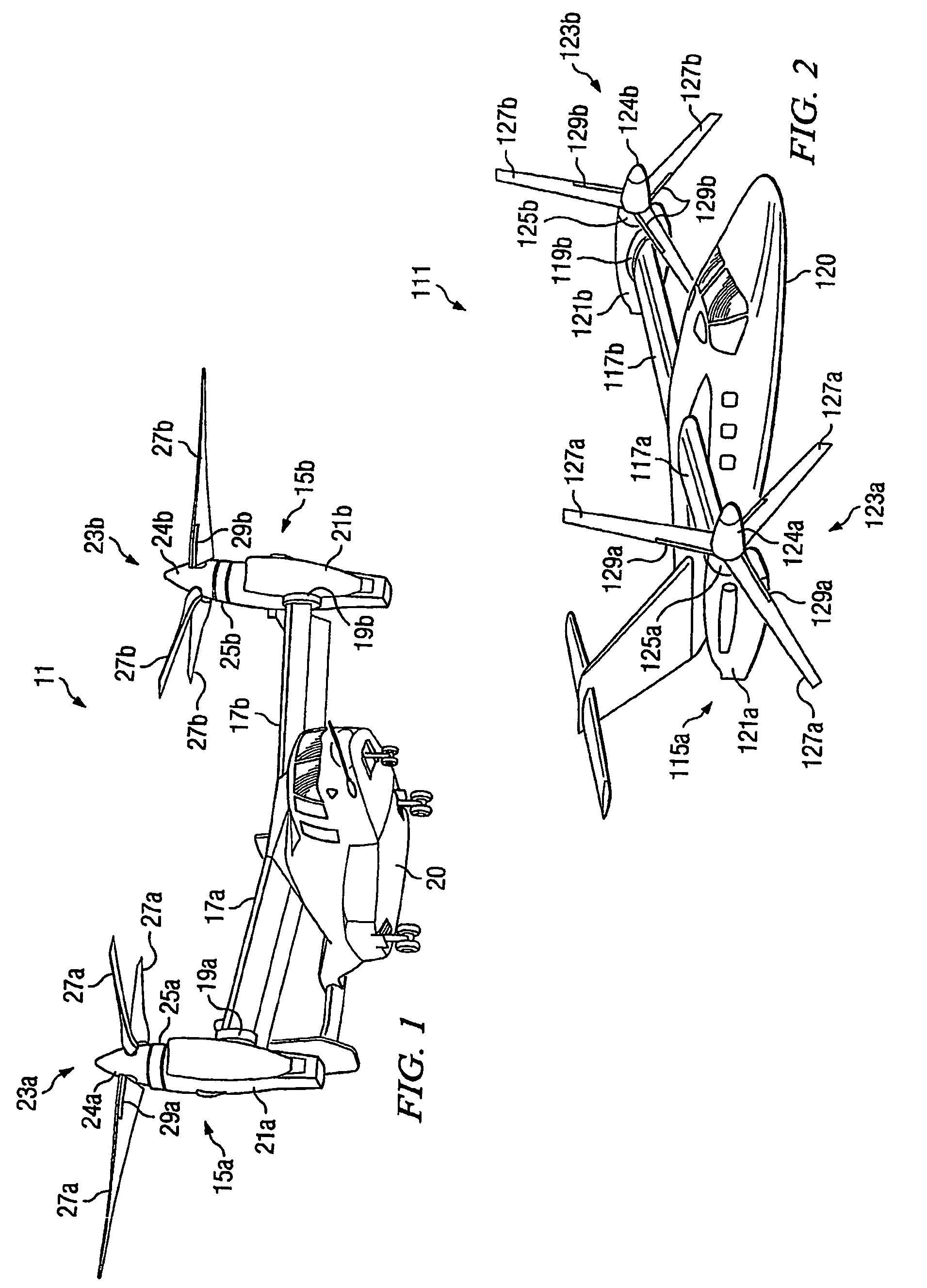
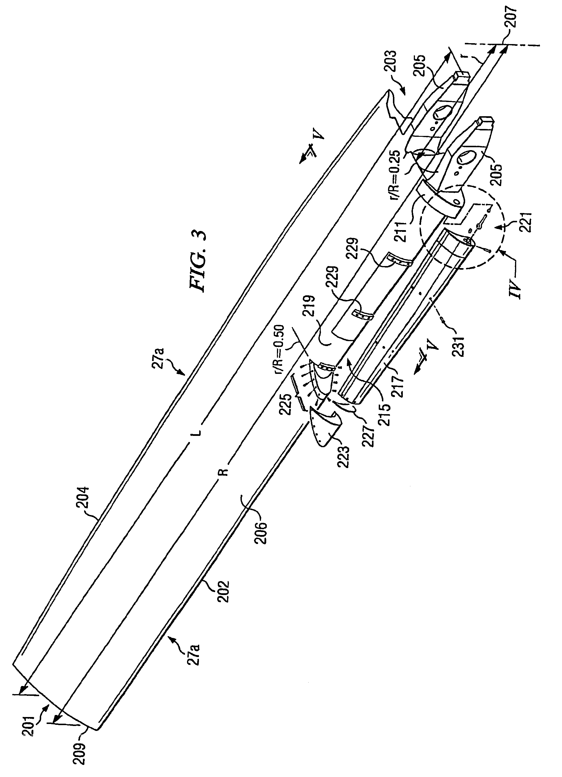
[0021]The present invention represents a means of improving hover maximum thrust capability without compromising the forward flight performance of a tiltrotor aircraft or other rotorcraft. Although the present invention is described with reference to tiltrotor aircraft, it should be understood that the present invention may be used on other types of rotorcraft, such as tilt wing and tail sitter aircraft. It will also be appreciated that both the civilian and military tiltrotor aircraft described herein may have two wing assemblies and two tiltrotor assemblies, or may be “Quad” type tiltrotor aircraft having four wing members and four tiltrotor assemblies.

[0022]There are several possible approaches to improving hover maximum thrust capability without compromising forward flight performance, including variable geometry rotors, on-blade controls, active twist, and high-lift airfoils, The present invention focuses on the area of high-lift airfoils.

[0023]Under the high-lift airfoil appro...


PUM


Abstract

A proprotor blade (27a, 27b, 127a, 127b) having a fixed, spanwise, leading edge slot (215) located in at least the inboard portion of the proprotor is disclosed. The slot (215) is formed by a selectively shaped slat (217) disposed in a selectively shaped recessed area (219) located at the leading edge (202) of the main portion of the proprotor blade. The slot (215) is selectively shaped so the a portion of the airflow over the lower airfoil surface of the proprotor blade is diverted between the main portion of the proprotor blade and the slat (217) and exits at the upper airfoil surface of the proprotor blade. The present invention may be used on both military-type tiltrotor aircraft (11) and civilian-type tiltrotor aircraft (111) with only minor variations to accommodate the different shapes of the proprotor blades.

Description

TECHNICAL FIELD[0001]The present invention relates to proprotors for tiltrotor aircraft and other rotorcraft. In particular, the present invention relates to proprotor blades with leading edge slots.DESCRIPTION OF THE PRIOR ART[0002]Tiltrotor aircraft are unique rotorcraft in that they have tiltrotor assemblies that operate between a helicopter mode in which the tiltrotor assemblies are rotated upward allowing the tiltrotor aircraft to take off, hover, fly, and land like a conventional helicopter; and an airplane mode, in which the tiltrotor assemblies are tilted forward allowing the tiltrotor aircraft to fly like a conventional fixed-wing propeller driven aircraft. The first tiltrotor aircraft were designed strictly for military purposes, but now efforts are being made to manufacture civilian-type tiltrotor aircraft, and “Quad” tiltrotor aircraft with two sets of wing assemblies and four tiltrotor nacelle assemblies.[0003]Because tiltrotor aircraft must operate in both the helicopt...

Claims


Application Information

Patent Timeline
Patent Type & Authority Patents(United States)
IPC IPC(8): B64C39/00B64C11/16B64C21/02B64C27/467B64C29/00
CPCB64C11/16B64C29/0033B64C27/467
Inventor ROBERTSON, DANIEL B.SMITH, DUDLEY E.HOLLIMON, CHARLES L.NARRAMORE, JIMMY C.MULLINS, ROBERT B.
Owner TEXTRON INNOVATIONS
Why Eureka
Try Eureka