Mobile universal hardware platform

a hardware platform and universal technology, applied in the direction of domestic cooling devices, electric apparatus casings/cabinets/drawers, instruments, etc., can solve the problems of significant processing and storage capabilities, inability to meet the needs of users, and inability to adjust the pitch of the rack unit as often limited, so as to achieve less complexity, less cost, and robust processing

Inactive Publication Date: 2012-09-04
BIRCHBRIDGE
View PDF65 Cites 15 Cited by
  • Summary
  • Abstract
  • Description
  • Claims
  • Application Information

AI Technical Summary

Benefits of technology

[0006]Embodiments of the present invention may provide an efficient way to cool and power components housed in a rack system. Thus, not only may more components be cooled for less cost and with less complexity, but very robust processing and storage capabilities may be provided in relatively smaller spaces. These advances may enable some embodiments having significant capability to be provided in a mobile environment.

Problems solved by technology

Another factor in determining component density is the pitch of the rack unit as often limited by the space required for component heat sinks and associated cooling components (e.g., fans).
A frequently underestimated problem when designing high-performance computer systems is the discrepancy between the amount of heat a system generates, particularly in high performance and high density enclosures, and the ability of its cooling system to remove the heat uniformly throughout the rack enclosure.
Due to the power requirements and heat removal requirements that often accompany standard blade servers, server banks are typically connected to fixed power and cooling sources and are therefore immobile.
However, certain use cases may require significant processing and storage capabilities to be mobile.
Thus, it may be difficult to provide adequate processing and storage capabilities for certain applications.
However, it should be noted that custom circuit and chip designs could also be used in the disclosed rack system design, but would not likely be as cost effective as using COTS components.
The result may be that potentially very large energy savings can be experienced over the life of the rack systems relative to conventional data systems.

Method used


Image

  • Mobile universal hardware platform
  • Mobile universal hardware platform
  • Mobile universal hardware platform

Examples


Embodiment Construction

[0019]Although an embodiment of the present invention has been described with reference to specific example embodiments, it will be evident that various modifications and changes may be made to these embodiments without departing from the broader spirit and scope of the invention. Accordingly, the specification and drawings are to be regarded in an illustrative rather than a restrictive sense.

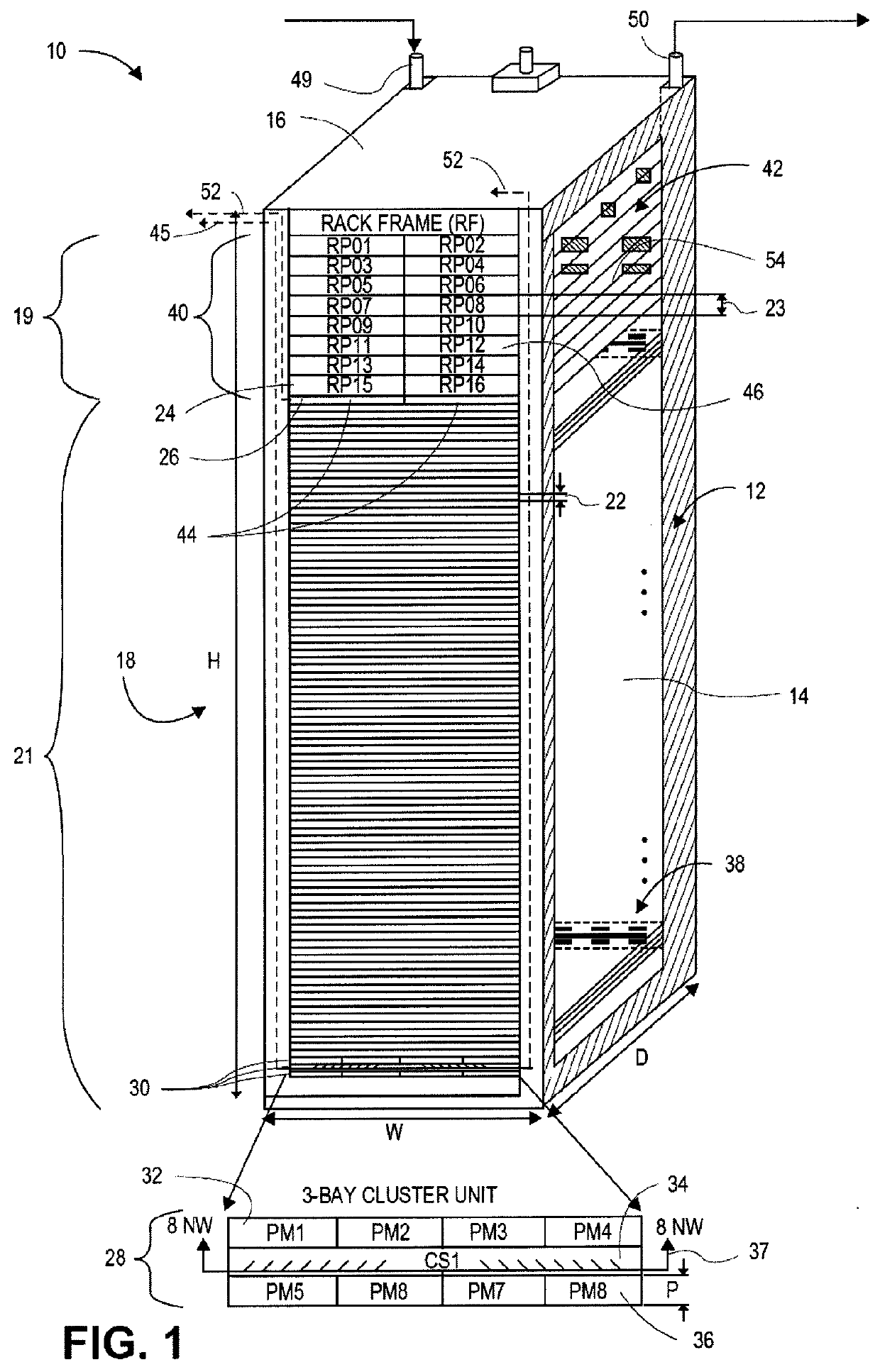
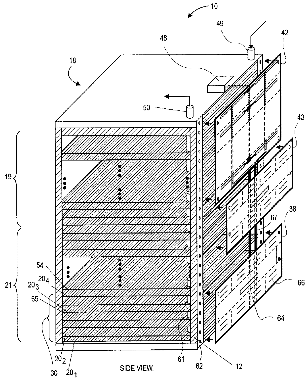
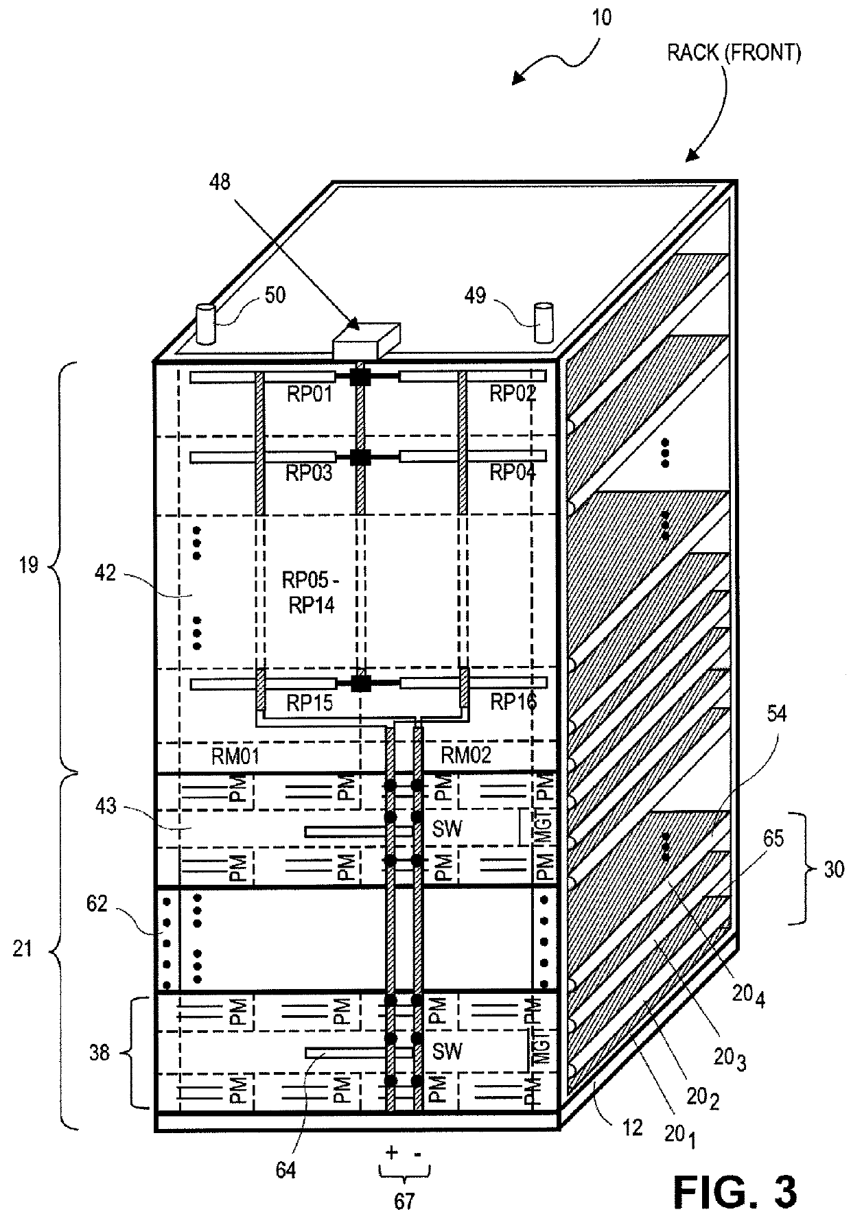
[0020]Embodiments of the present invention generally relate to an architecture for a scalable modular data system. In this regard, embodiments of the present invention relate to a rack system (e.g., rack system 10) that may contain a plurality of service units or modules. The rack system described herein provides physical support, power, and cooling for the service units or modules contained therein. The rack system also provides a set of interfaces for the service units or modules including mechanical, thermal, electrical, and communication protocol specifications. Moreover, the rack system de...


PUM


Abstract

A mobile container may include a bottom element, a top element, a front element, a back element, and two side elements defining a containment volume. The two side elements may have a length longer than a length of either the front element or the back element. The containment volume may be configured to include a plurality of rack frames. Each rack frame may include a module insertion area on a first side of the rack frame, a universal backplane area, and a power bus. The universal backplane area may be positioned on a second side of the rack frame opposite to the first side and may include at least one mounting surface configured to mount two or more backplane boards. At least two of the backplane boards may be configured to couple to two respective modules that each have at least two different functions and are insertable through the module insertion area. The at least two different functions of at least one backplane board may include rack power and management functions. The power bus may provide power to the two or more backplane boards mounted in the universal backplane area.

Description

RELATED APPLICATION[0001]This application is related to U.S. patent application Nos. 12 / 840,788, 12 / 840,808, 12 / 840,824, 12 / 840,842, and 12 / 840,871, each of which was filed Jul. 21, 2010, and each of which are incorporated herein by reference in their entirety.FIELD[0002]One embodiments of the present invention may relate to providing a universal hardware platform that is mobile.BACKGROUND[0003]Current standard rack configurations are measured in rack-units (RUs). For example, a blade server may have a rack unit measuring 19 inches wide and having a pitch of 1.75 inches in height. A common computer rack form-factor is 42 RU high, which is a factor in limiting the density or number of components directly mountable into a rack. Higher density component systems are desirable since they require less space per rack enclosure and ultimately less space within the building housing the enclosures. Often these buildings must include high price high maintenance false floors to accommodate the ...

Claims


Application Information

Patent Timeline
Patent Type & Authority Patents(United States)
IPC IPC(8): H05K7/20H05K7/14H05K7/10
CPCH05K7/1488H05K7/1497
Inventor DUNWOODY, JOHN CRAIGDUNWOODY, TERESA ANN
Owner BIRCHBRIDGE
Why Eureka
Try Eureka