Methods and systems for obstacle detection using structured light

a structured light and obstacle detection technology, applied in the field of methods and systems for obstacle detection using structured light, can solve the problems of disadvantage, relatively high cost of devices, and inability of sensors to detect objects,

Active Publication Date: 2015-06-18
IROBOT CORP
View PDF1 Cites 143 Cited by
  • Summary
  • Abstract
  • Description
  • Claims
  • Application Information

AI Technical Summary

Benefits of technology

[0017]The methods and systems for obstacle detection disclosed herein use the structured light approach, in which novel methods and systems for light detection and for sensor placement enable the robust detection of obstacles in applications where other methods would either not be permitted (due to eye safety restrictions), or would not function satisfactorily.
[0023]The light source can be any of a number of devices including laser and light emitting diodes. The beam of light generated by the source is generally pulsed in a repetitious on and off sequence or in accordance with a pseudo-random code. The structured light projected by the light source on the path before the robot may include focused points of light or lines of light arrayed horizontally, vertically, or both. Based on the location of the reflected light in the combined images, the processing unit can use triangulation, for example, to determine the position and / or height of the reflection and distinguish between the floor and an obstacle in the robot's path. In some embodiments, the obstacle detector further includes a tilt sensor configured to determine the orientation of the robots to further enhance the accuracy of the obstacle detector.

Problems solved by technology

Despite the relatively high quality of the data, the device is relatively expensive, precluding its use in many products.
Furthermore, the scan is done only in one plane (typically a horizontal plane if the laser range finder is horizontally mounted); thus, the sensor is unable to detect objects that do not lie in the scan plane (such as a tabletop).
Because IR sensors only provide detection along the pencil-like beam, it is, disadvantageously, relatively difficult to obtain complete coverage of the environment, even when a relatively large number of IR sensors, such as dozens of IR sensors, are used.
However, using ultrasound sensors, it is relatively difficult to localize an object precisely, to disambiguate between various objects at different distances, and to disambiguate echoes from true objects.
A challenging part of this process is determining the correct correspondences of features seen in one image with what is seen in other images.
This is a relatively computationally intensive process, which can often produce inaccurate results, particularly when the environment being imaged has relatively little texture (i.e., features, or points that can easily be identified across images).
The method of detecting corresponding image points and the method of triangulation are the same as in stereo vision, but the problem is made more difficult because the spatial co-location of the imager when the images were acquired is, a priori, not known.
Even if the motion of the mobile device is somehow measured, it is typically not known with sufficient accuracy to enable accurate triangulation.
The overall method is of comparable computational cost and complexity as the stereo vision method, and the method suffers from the same drawback, in that it typically does not provide reliable and complete estimates when there is insufficient texture in the environment.
One challenge of this method is to reliably detect the illumination pattern.
A typical difficulty is that the pattern must remain visible to the imager even in the presence of other light sources, such as the sun in the case of an outdoor environment.
In some applications this may not be feasible, due to power considerations or due restrictions on illumination intensity required by eye safety standards.
The use of such a filter, however, precludes the use of the imager for other purposes for which other frequencies of light are necessary.
However, once again, this method precludes the use of the imager for other purposes for which other frequencies of light are necessary.
However, it works effectively only if there is neither motion of the imager nor motion of anything else in the environment.
Any moving object (or apparent moving environment if the imager itself is moving) will register in the difference of images, making it relatively difficult to detect the illumination pattern.
Furthermore, many indoor lighting sources connected to alternating current sources experience power flicker (in the case of fluorescent lights) or fluctuate (in the case of incandescent lights), typically at 50 Hz or 60 Hz, which also violates the assumption that nothing but the pattern illumination source varies between the two acquired images.

Method used


Image

  • Methods and systems for obstacle detection using structured light
  • Methods and systems for obstacle detection using structured light
  • Methods and systems for obstacle detection using structured light

Examples


Embodiment Construction

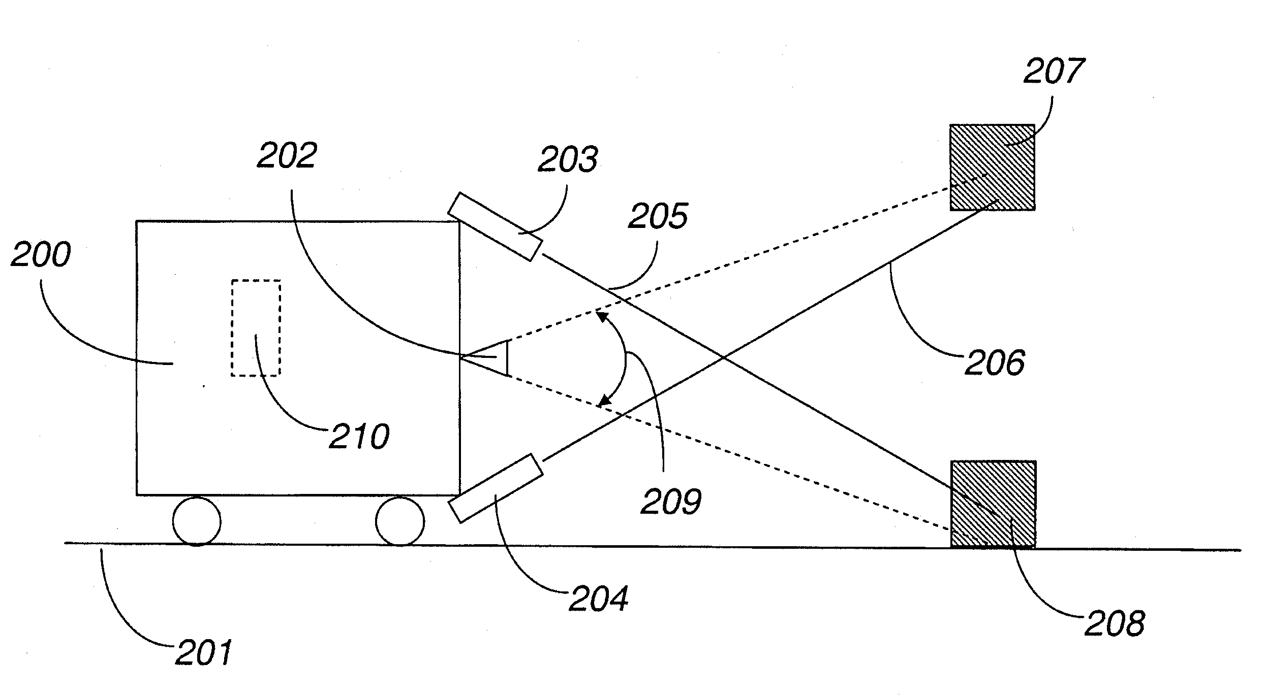
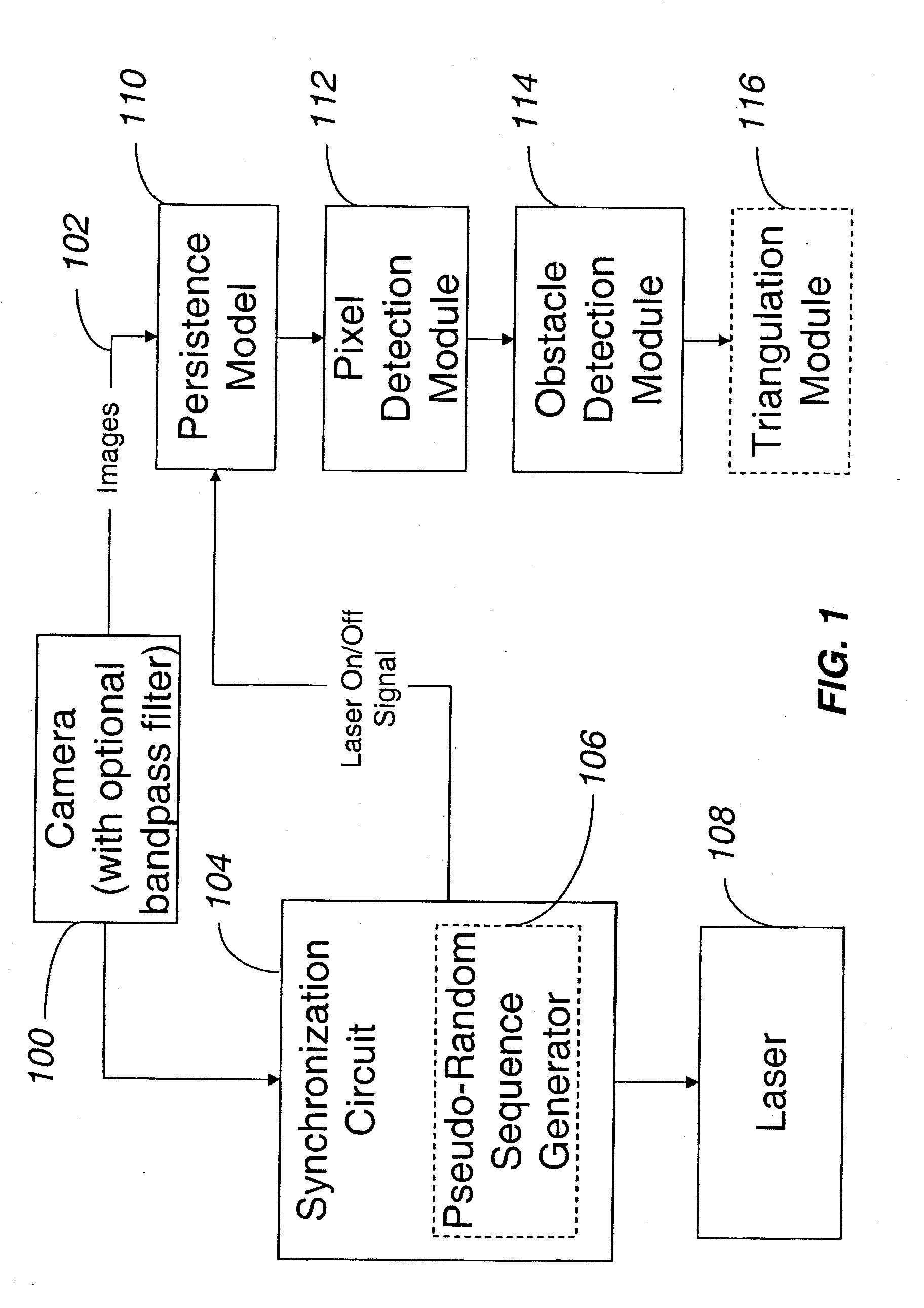
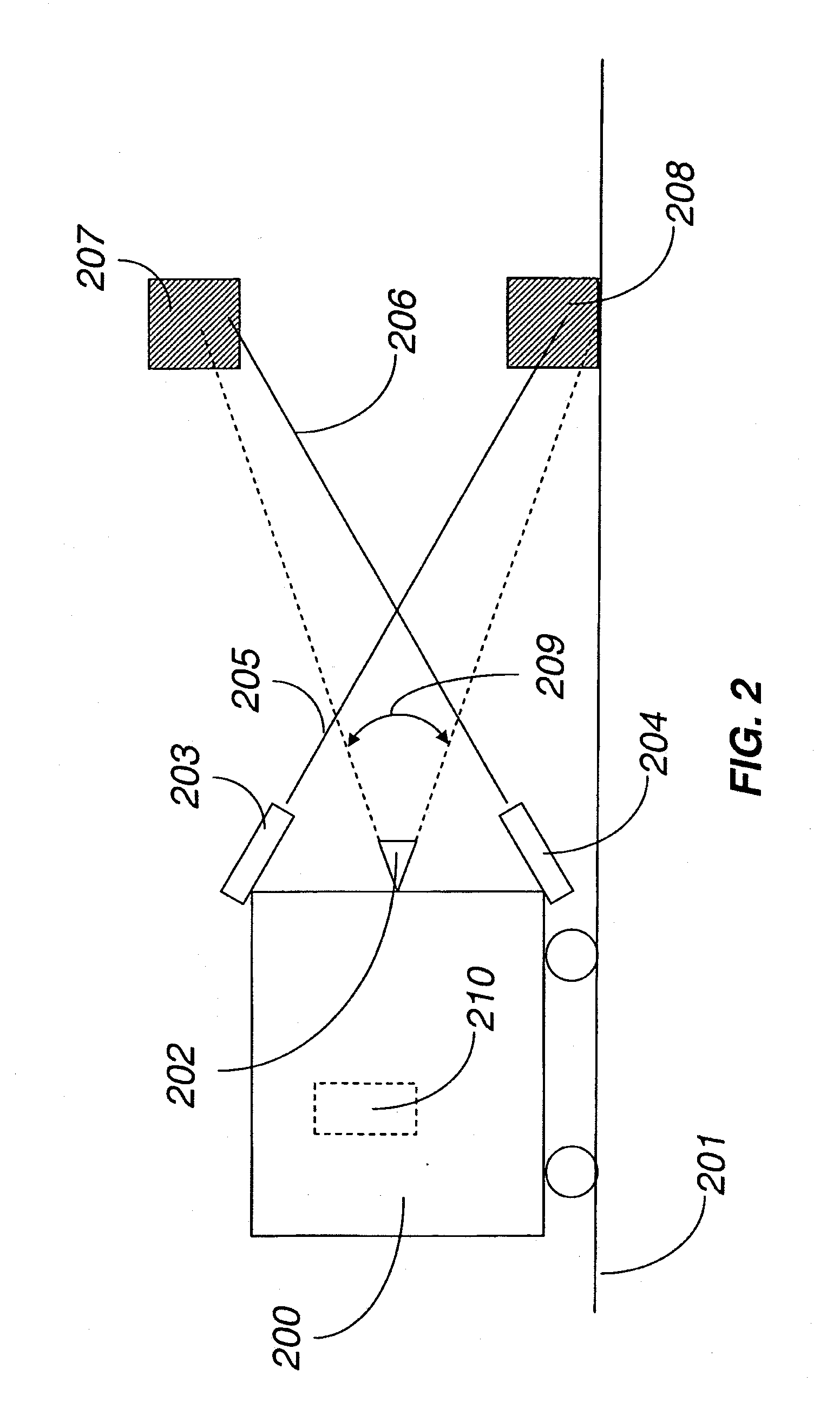
[0032]FIG. 1 illustrates a block diagram for one embodiment of the invention. The system includes a visual sensor 100 optionally equipped with a narrow bandpass interference filter matching the frequency of the lasers 108. A synchronization circuit 104 receives a synchronization signal from a visual sensor 100 and sequentially pulses a laser 108 on and off. Optionally, the synchronization circuit 104 includes a pseudo-random sequence generator 106. A stream of images 102 acquired from the visual sensor 100 is sent to a persistence model module 110, which combines the information from the stream of images 102. A pixel detection module 112 determines which pixels in the images 102 are illuminated by light from the laser 108, namely the light reflected from the path of the robot. An obstacle detection module 114 then decides whether the illuminated pixels correspond to one or more obstacles or do not correspond to an obstacle. For example, in one embodiment, if the obstacle detection m...


PUM


Abstract

An obstacle detector for a mobile robot while the robot is in motion is disclosed. The detector preferably includes at least one light source configured to project pulsed light in the path of the robot; a visual sensor for capturing a plurality of images of light reflected from the path of the robot; a processing unit configured to extract the reflections from the images; and an obstacle detection unit configured to detect an obstacle in the path of the robot based on the extracted reflections. In the preferred embodiment, the reflections of the projected light are extracted by subtracting pairs of images in which each pair includes a first image captured with the at least one light source on and a second image captured with the at least one light source off, and then combining images of two or more extracted reflections to suppress the background.

Description

INCORPORATION BY REFERENCE TO ANY PRIORITY APPLICATIONS[0001]Any and all applications for which a foreign or domestic priority claim is identified in the Application Data Sheet as filed with the present application are hereby incorporated by reference under 37 CFR 1.57.BACKGROUND OF THE INVENTION[0002]1. Field of the Invention[0003]This disclosure presents a system and method through which a mobile device, such as a robot, can detect obstacles while navigating in an environment using a laser pattern to augment the visible field of a visual sensor and measure the distance to objects.[0004]2. Description of the Related Art[0005]To create a robust collision detection system, an algorithmic approach using only a video feed is unlikely to detect all near-field objects with a reliability preferred for robotic navigation.[0006]Automatic obstacle detection is a useful functionality for a mobile device that navigates in an environment. For fully autonomous devices, automatic obstacle detecti...

Claims


Application Information

Patent Timeline
Patent Type & Authority Applications(United States)
IPC IPC(8): G05D1/02G01S17/04G01S17/86G01S17/89G01S17/931
CPCG05D1/0248Y10S901/01G05D1/0274G01S17/89G01S7/483G01S17/04G01S17/931G05D1/0246G05D1/0253G01S17/86G05D1/0038G05D2201/0209G05D2201/0211
Inventor HICKERSON, KEVINGONCALVES, LUISPIRJANIAN, PAOLOROMANOV, NIKOLAI
Owner IROBOT CORP
Why Eureka
Try Eureka