Bicycle shoe cleat for clipless pedals

a technology of clip-on pedals and shoes, which is applied in the direction of footwear, vehicle cranks, vehicle components, etc., can solve the problem that the shoes for the pedals of racing bicycles cannot be used to the pedals of mountain bicycles

Active Publication Date: 2021-06-03
CYCLINGDEAL USA INC
View PDF0 Cites 4 Cited by
  • Summary
  • Abstract
  • Description
  • Claims
  • Application Information

AI Technical Summary

Benefits of technology

The technical effect of this patent is that it describes an improved method or system related to a certain technology. This improvement can be beneficial in various ways such as making things faster, easier, or better.

Problems solved by technology

The technical problem addressed by this patent is that there are specialized types of bicycle shoes for mountaineering and road cycling, but they don't work together easily because the clipplets on the shoes aren't compatible. This results in users having to purchase separate pairs of shoes for each activity, even if some parts may fit between them. The solution proposed is a new kind of clip that allows for easy connection between the shoe and the bike pedal, making it possible to switch between mountain and road activities without buying multiple sets of shoes.

Method used


Image

  • Bicycle shoe cleat for clipless pedals
  • Bicycle shoe cleat for clipless pedals
  • Bicycle shoe cleat for clipless pedals

Examples


Embodiment Construction

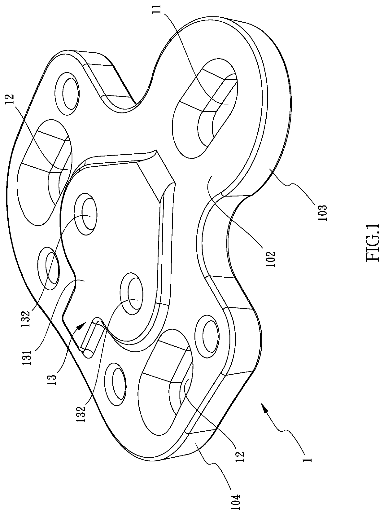
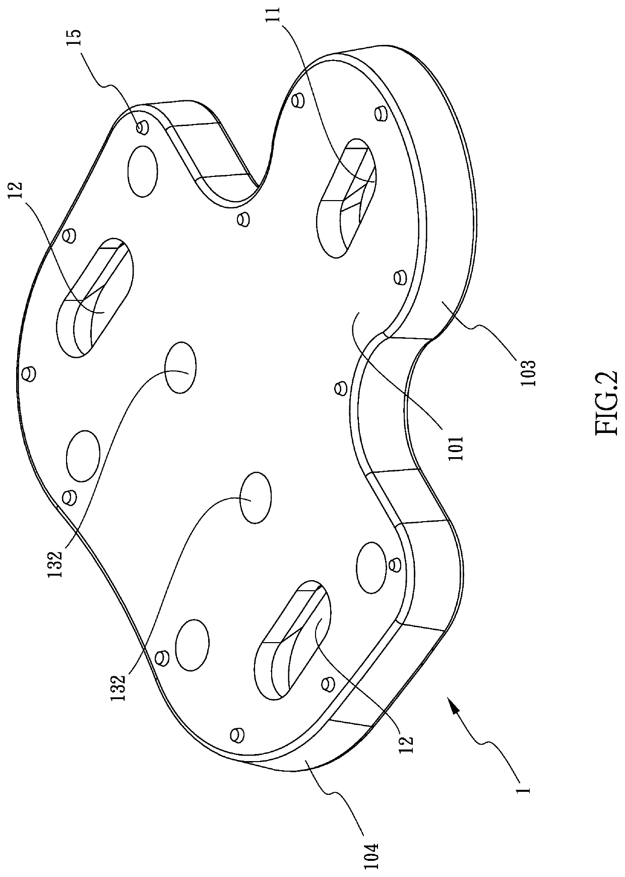
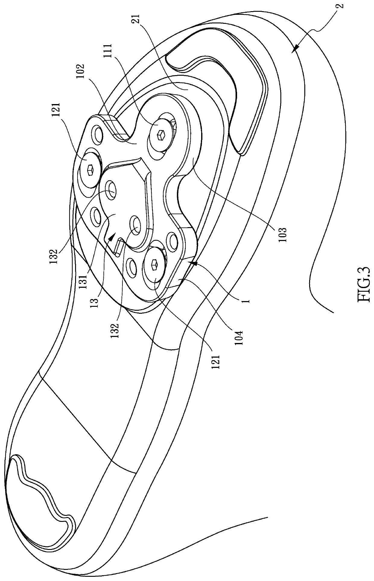
[0015]Referring to FIGS. 1 to 5, the bicycle shoe cleat 1 of the present invention comprises a first surface 101 and a second surface 102 which is located opposite to the first surface 101. The first surface 101 is to be connected to a racing bicycle shoe 2. The second surface 102 is connected to an engaging member 3 which is to be connected with a mountain bicycle pedal. The bicycle shoe cleat 1 has a front portion 103 and a rear portion 104 which is wider than the front portion 103. A first slot 11 is defined through the first and second surfaces 101, 102 of the front portion 103. Two second slots 12 are defined through the first and second surfaces 101, 102 of the rear portion 104. The axis of the first slot 11 and two respect axes of the two second slots 12 are parallel to each other. A first bolt 133 extends through the first slot 11 and is connected to the outsole 21 of the racing bicycle shoe 2. Two second bolts 121 extend through the two second slots 12 and are connected to ...


PUM


Abstract

A bicycle shoe cleat includes a first slot defined through a front portion of the bicycle shoe cleat, and two second slots defined through a rear portion of the bicycle shoe cleat. Bolts extend the first and second slots, and are connected to the outsole of a racing bicycle shoe. A protrusion extends from one of two surfaces of the rear portion and has a convex and curved outer surface. A stepped portion is formed between the protrusion and the rear portion. Two bores are defined through the protrusion and the bicycle shoe cleat. Two fixing bolts extend through an engaging member and are connected to the two bores. The bicycle shoe cleat and the engaging member are installed to a racing bicycle shoe and can be clipped to clipless pedals of mounting bikes.

Description


Claims


Application Information

Patent Timeline
Owner CYCLINGDEAL USA INC
Why Eureka
Try Eureka