
Electronic monitoring system and control method thereof

a monitoring system and electronic technology, applied in the field of electronic monitoring systems and control methods thereof, can solve the problems of inability to quickly cope with recrime, ineffective in lowering the recrime rate of the person to be monitored, and inability to effectively supervise and manage. , to achieve the effect of minimizing social and economic costs and effective supervision and managemen

Active Publication Date: 2021-07-08
LIFE SCI TECH
View PDF3 Cites 0 Cited by
  • Summary
  • Abstract
  • Description
  • Claims
  • Application Information

AI Technical Summary

Benefits of technology

The present invention provides an electronic monitoring system and control method that can effectively supervise and manage a person to be monitored by detecting their location and the status of their electronic monitoring device. The system can also analyze the person's behavior pattern and detect abnormal behavior in advance, preventing crimes and minimizing social and economic costs.

Problems solved by technology

However, such a system has a wide error range of location information such as GPS information, and provides only information on the simple movements (for example, walking, running, lying down, stopping and the like) of a person to be monitored, so there are limitations in its usability and accuracy.
In addition, there was a problem that it was not effective in lowering the recrime rate of the person to be monitored, who is the wearer of the electronic anklet, because it was not possible to preemptively cope with abnormal signs in the behavior of the person to be monitored, and it was not capable of promptly coping with the recrime of the wearer of the electronic anklet.
In addition, in the conventional system, the location tracking of the person to be monitored who wears the electronic anklet is only figuring out the access to the address of the previously registered place, so that there was a problem that it is not possible to effectively warn the victim against the recidivism of the person to be monitored.

Method used


Image

  • Electronic monitoring system and control method thereof
  • Electronic monitoring system and control method thereof
  • Electronic monitoring system and control method thereof

Examples


Embodiment Construction

[0032]Hereinafter, the embodiments of the present invention will be described in detail with reference to the accompanying drawings so that those of ordinary skill in the art to which the present invention belongs can easily practice the present invention. However, the present invention can be implemented in various different forms and is not limited to the embodiments described herein. In addition, in the drawings, parts irrelevant to the description are omitted in order to clearly describe the present invention, and similar drawing symbols are assigned to similar parts throughout the specification.

[0033]Throughout the specification, when a part “includes” a certain component, it means that other components may be further included rather than excluding other components unless specifically stated to the contrary.

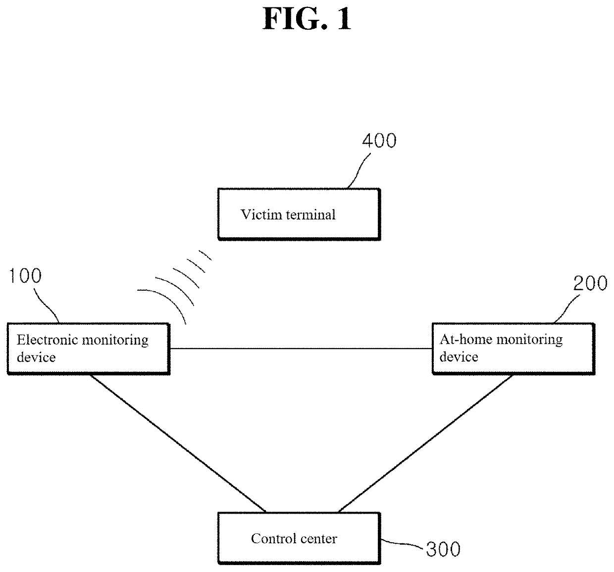
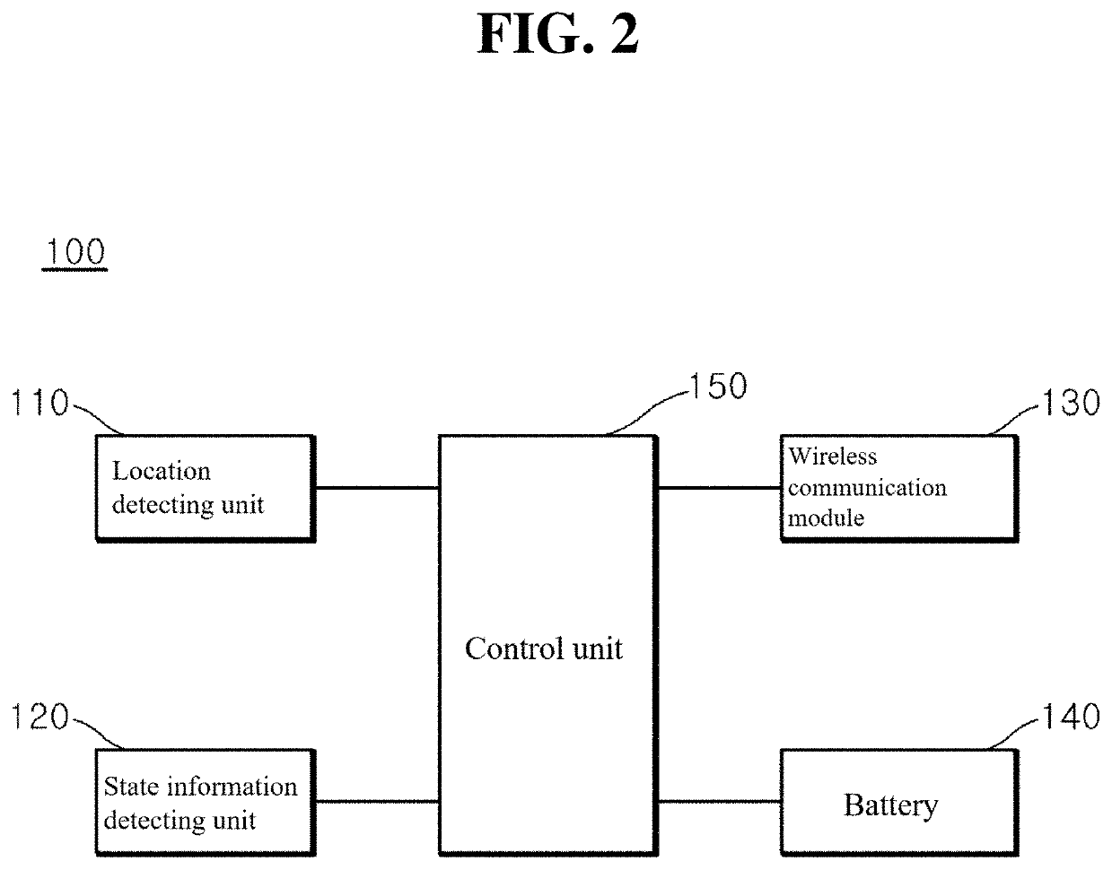
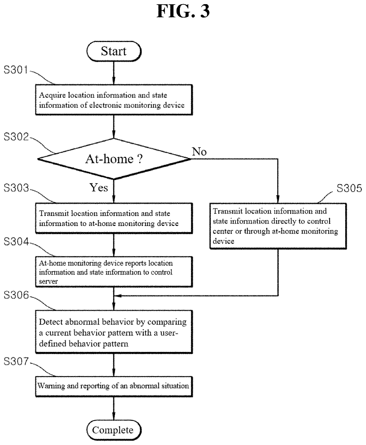
[0034]FIG. 1 is a block diagram showing the electronic monitoring system according to one embodiment of the present invention, FIG. 2 is a block diagram showing the configur...


PUM


Abstract

An electronic monitoring system includes an electronic monitoring device that is worn on a part of the body of a person to be monitored, to acquire location information and state information; an at-home monitoring device that receives the location information and the state information provided from the electronic monitoring device and determines whether the electronic monitoring device is at home, on the basis of the location information; and a control center that receives the location information and the state information from at least one of the electronic monitoring device or the at-home monitoring device to manage the person to be monitored.

Description

CROSS-REFERENCE TO RELATED APPLICATION[0001]This application is a Continuation of International Application No. PCT / KR2018 / 011227 filed on Sep. 21, 2018, which application is incorporated herein by reference in its entirety.TECHNICAL FIELD[0002]The present invention relates to an electronic monitoring system and a control method thereof, and more specifically, the present invention relates to an electronic monitoring system and a control method thereof that is capable of effectively supervising and managing a person to be monitored through an electronic monitoring device that is implemented integrally with an electronic anklet and the like and is worn on a part of the body of a person to be monitored.[0003]RELATED ART[0004]Recently, as sexual crimes such as violent sexual assaults are increasing day by day, voices demanding strong countermeasures against recidivism to cope with such violent crimes are increasing day by day. Thus, sex offenders who are released after the sentence of ...

Claims


Application Information

Patent Timeline
IPC IPC(8): G08B25/10H04W4/029G16Y40/10G16Y10/80
CPCG08B25/10G16Y10/80G16Y40/10H04W4/029G06Q50/26G06N3/02G06Q50/10G08B21/22H04W4/80
Inventor KIM, JEONG HWANCHOI, MIN JOONYEO, SEUNG YUNNOH, II SUKYOON, HYUN BONG
Owner LIFE SCI TECH
Learn More