Fixing Device for Detachably Fixing a Body to a Motor Vehicle, and Luggage-Carrying Device

Pending Publication Date: 2021-08-26
BAYERISCHE MOTOREN WERKE AG
0 Cites 0 Cited by

AI-Extracted Technical Summary

Problems solved by technology

The electrical line which is guided from the vehicle component to the body must be joined and detached again ma...

Benefits of technology

[0021]Furthermore, the first coupling element and/or the second coupling element can comprise at least one tensioning means, in order to be able to tension the first fixing device and/or the second fixing device. In this way, movement of the body can be reduced as a result of the application of a tensioning force.
[0022]In order to prevent penetration of dirt or moisture to the first conductor or the second conductor, it proves to be adv...

Abstract

A fixing device for detachably fixing a body to a vehicle, such as a tilting vehicle, includes: at least one first fixing device which can be fixed or is fixed to the body; at least one second fixing device which can be fixed or is fixed to a load-bearing vehicle component of the motor vehicle and which is detachably joined to the first fixing device in a coupled arrangement in order to fix the body to the vehicle component; and at least one electrical line which can be guided from the vehicle component to the body and can be fixed to the body in order to supply an electrical load. The fixing device is characterized in that the first fixing device has a first conductor of the electrical line and the second fixing device has a second conductor of the electrical line. The first conductor and the second conductor can be electrically conductively connected or are electrically conductively connected to one another in the coupled arrangement of the fixing devices.

Application Domain

Technology Topic

Image

  • Fixing Device for Detachably Fixing a Body to a Motor Vehicle, and Luggage-Carrying Device
  • Fixing Device for Detachably Fixing a Body to a Motor Vehicle, and Luggage-Carrying Device
  • Fixing Device for Detachably Fixing a Body to a Motor Vehicle, and Luggage-Carrying Device

Examples

  • Experimental program(1)

Example

DETAILED DESCRIPTION OF THE DRAWINGS
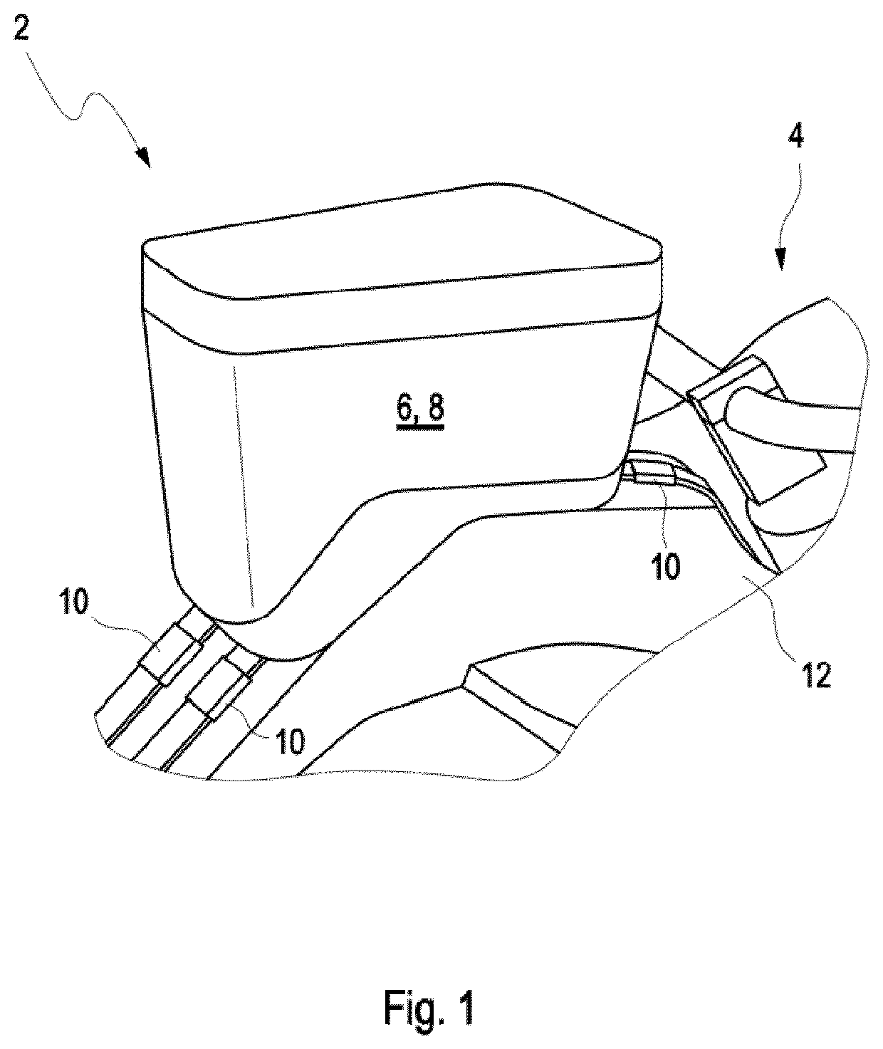
[0033]FIG. 1 shows a luggage-carrying device, provided overall with the designation 2, which can be arranged on a motor vehicle 4. The luggage-carrying device 2 comprises a body 8 which is formed as a luggage container 6 and which can be fixed to a vehicle component 12 of the motor vehicle 4 by at least one fixing device 10.
[0034]FIG. 1 shows an exemplary embodiment of the luggage-carrying device 2 in which the luggage-carrying device 2 comprises a total of three fixing devices 10.
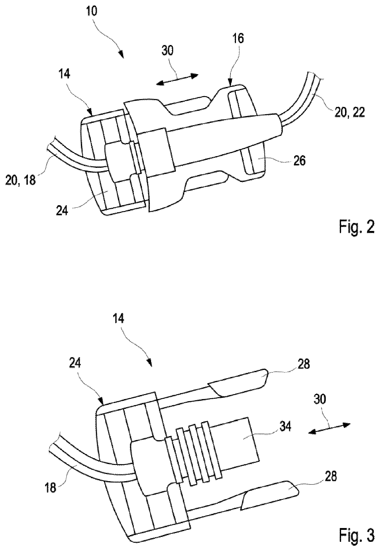
[0035]An embodiment of the fixing device 10 will now be discussed by using FIGS. 2 to 5.
[0036]FIG. 2 shows a fixing device 10 in a joined arrangement. In the latter, a first fixing device 14 is fixed to a second fixing device 16 in a coupled manner. Furthermore, a first conductor 18 of an electrical line 20 is integrated into the first fixing device 14. A second conductor 22 of the line 20 is integrated into the second fixing device 18.
[0037]FIG. 2 shows an exemplary embodiment of the fixing device 10 in which the first fixing device 14 and the second fixing device 16 comprise a section that can be bent flexibly transversely to its longitudinal direction. The first fixing device 14 comprises a first coupling element 24, to which the second fixing device 16 can be fixed detachably by a second coupling element 26. For this purpose, the first coupling element 24 of the first fixing device 14 in the exemplary embodiment 2 that can be seen in the figures comprises snap-in members 28, which are movable transversely to the joining direction 30 and, in the coupled arrangement, can engage in at least one recess 32 of the second coupling element 26 counter to the joining direction 30, forming a catch.
[0038]Furthermore, the first coupling element 24 comprises a first contact section 34 of the first conductor 18 which, in the joined arrangement of the fixing means 14, 16, is joined to a second contact section 36 of the second conductor 22 so as to make contact. The electrical line 20 is formed in this way.
[0039]FIG. 3 shows a detailed view of the first coupling element 24 with its two snap-in members 28 and the first contact section 34.
[0040]FIG. 4 shows a detailed view of the second coupling element 26 having the two recesses 32, into which the snap-in members 28 of the first coupling element 24 can be latched in the joined arrangement, and having the second contact section 36 of the second conductor 22.
[0041]FIG. 5 shows a plan view of the exemplary embodiment of the second coupling element 26 according to FIG. 4.
[0042]The action of the fixing device 10 and the luggage-carrying device 2 will be explained briefly below.
[0043]When arranging a body 8 formed as a luggage container 6 on a vehicle component 12 of the motor vehicle 4, the first fixing device 14 fixed to the body 8 is fixed to the second fixing device 16 connected to the vehicle component 12. In this way, the body 8 formed as a luggage container 6 is fixed to the motor vehicle 4.
[0044]At the same time as the first fixing device 14 is joined to the second fixing device 16, the first conductor 18 is electrically connected to the second conductor 22, which means that the two conducting means 18, 22 form the electrical line 20. By means of the electrical line 20, an electrical load arranged in the body 8 formed as a luggage container 6 can be connected to an electrical energy source arranged in the motor vehicle 4 and supplied with electrical energy.
[0045]The features of the invention disclosed in the above description, in the claims and in the drawing can be essential both individually and also in any desired combination in the implementation of the invention in its various embodiments.
LIST OF DESIGNATIONS
[0046] 2 Luggage-carrying device [0047] 4 Motor vehicle [0048] 6 Luggage container [0049] 8 Body [0050] 10 Fixing device [0051] 12 Vehicle components [0052] 14 First fixing device [0053] 16 Second fixing device [0054] 18 First conductor [0055] 20 Electrical line [0056] 22 Second conductor [0057] 24 First coupling element [0058] 26 Second coupling element [0059] 28 Snap-in member [0060] 30 Joining direction [0061] 32 Recess [0062] 34 First contact section [0063] 36 Second contact section

PUM

no PUM

Description & Claims & Application Information

We can also present the details of the Description, Claims and Application information to help users get a comprehensive understanding of the technical details of the patent, such as background art, summary of invention, brief description of drawings, description of embodiments, and other original content. On the other hand, users can also determine the specific scope of protection of the technology through the list of claims; as well as understand the changes in the life cycle of the technology with the presentation of the patent timeline. Login to view more.

Similar technology patents

Extrusion mould

InactiveCN108114997AReduce extrusion pressureReduce movementExtrusion diesMaterials scienceExtrusion
Owner:FUJIAN NANPING ALUMINUM +1

Classification and recommendation of technical efficacy words

  • Prevent penetration
  • Reduce movement

Redox flow secondary battery and electrolyte membrane for redox flow secondary battery

ActiveUS20140370404A1High ion selectivityPrevent penetrationElectrolyte holding meansNon-metal conductorsPorous membraneBarrier membrane
Owner:ASAHI KASEI KK

Hole saw with depth stop

InactiveUS20080187405A1Prevent penetrationDeep penetrationThread cutting toolsDrilling/boring measurement devicesDepth of penetrationFixed position
Owner:GREENLEE TEXTRON
Why Eureka
Try Eureka