
Method and apparatus for selectively injecting fibre material from multiple chambers into a single chamber

a technology of fibre material and single chamber, which is applied in the field of textile machinery, can solve the problems of loss in material quality, and other disadvantages of conventional processes, and achieve the effect of improving the blow room process in spinning facilities

Pending Publication Date: 2021-09-02
SUTARIA TARANG J
View PDF2 Cites 0 Cited by
  • Summary
  • Abstract
  • Description
  • Claims
  • Application Information

AI Technical Summary

Benefits of technology

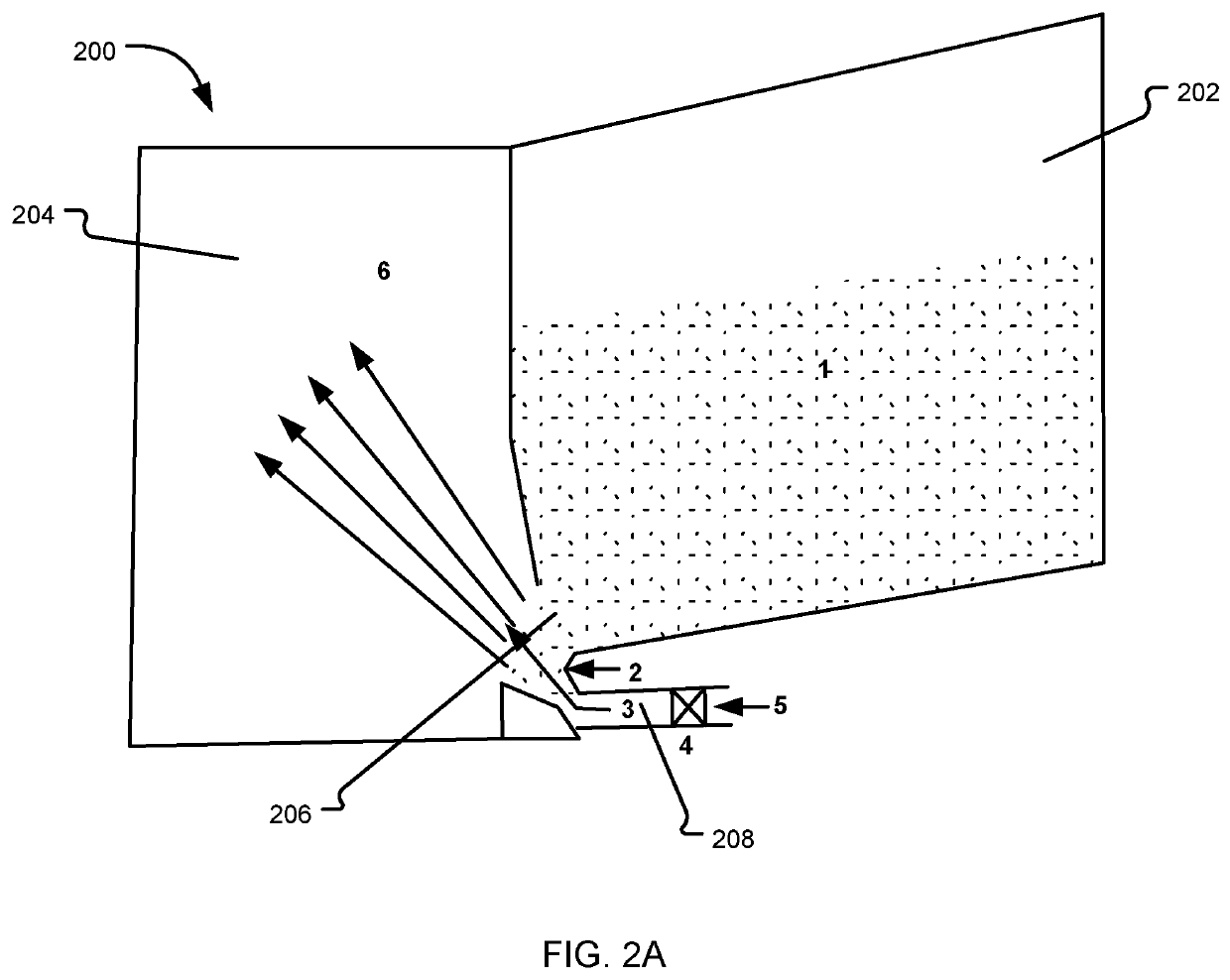
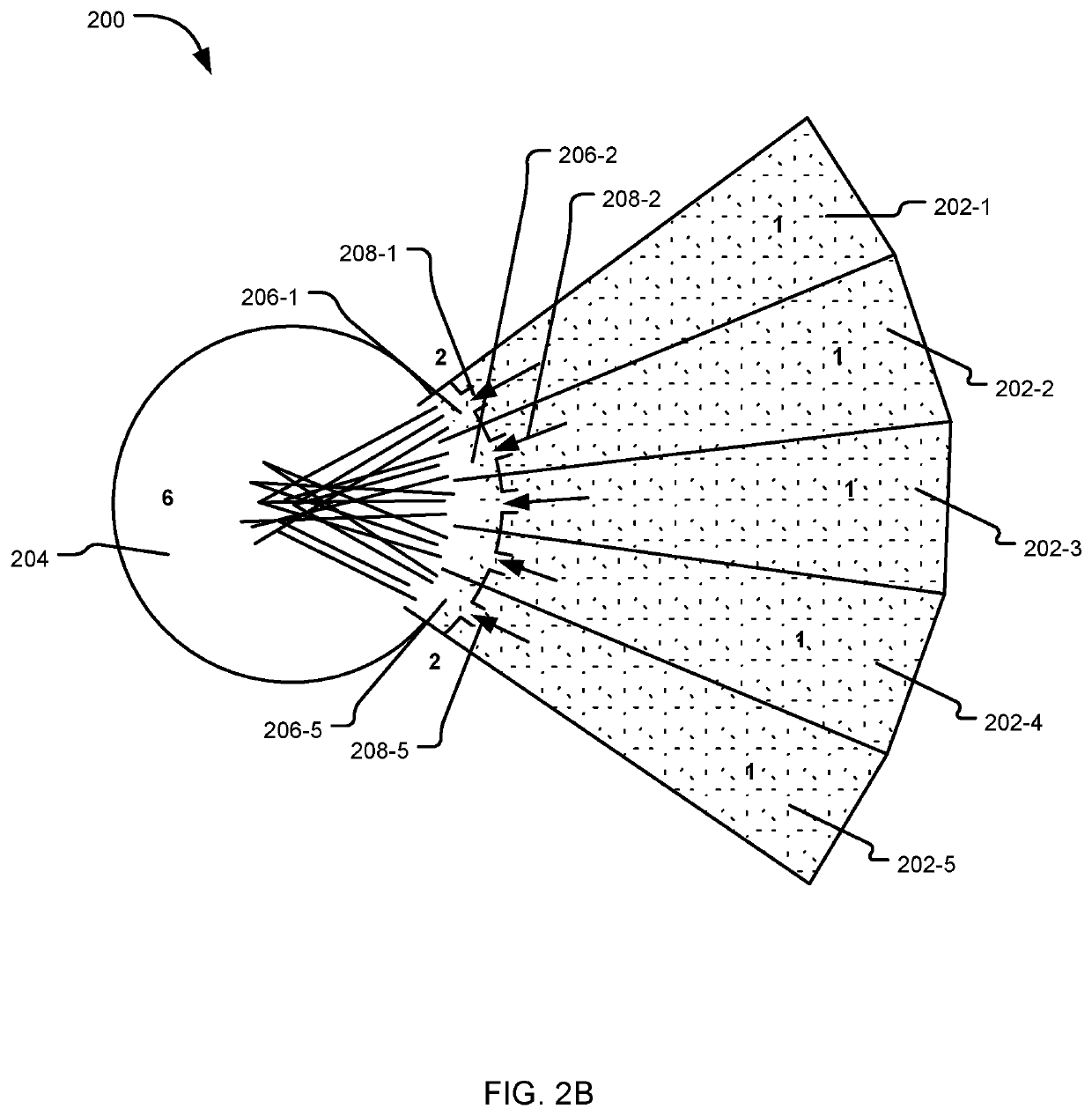
The present disclosure aims to improve the processes in spinning facilities by selectively injecting fibre material from multiple chambers into a single chamber. This method and apparatus do not use spiked rollers and prevent breakage of fibers, which improve the quality of the material. The use of bursts of pressurized air or gas helps in opening the tufts of fibro and cleaning them simultaneously, improving the efficiency of the processing stages. In addition, the method includes controlling the jets of the pressurized gaseous fluid to create bursts of short durations for opening the fibre material and spreading it into the mixing chamber.

Problems solved by technology

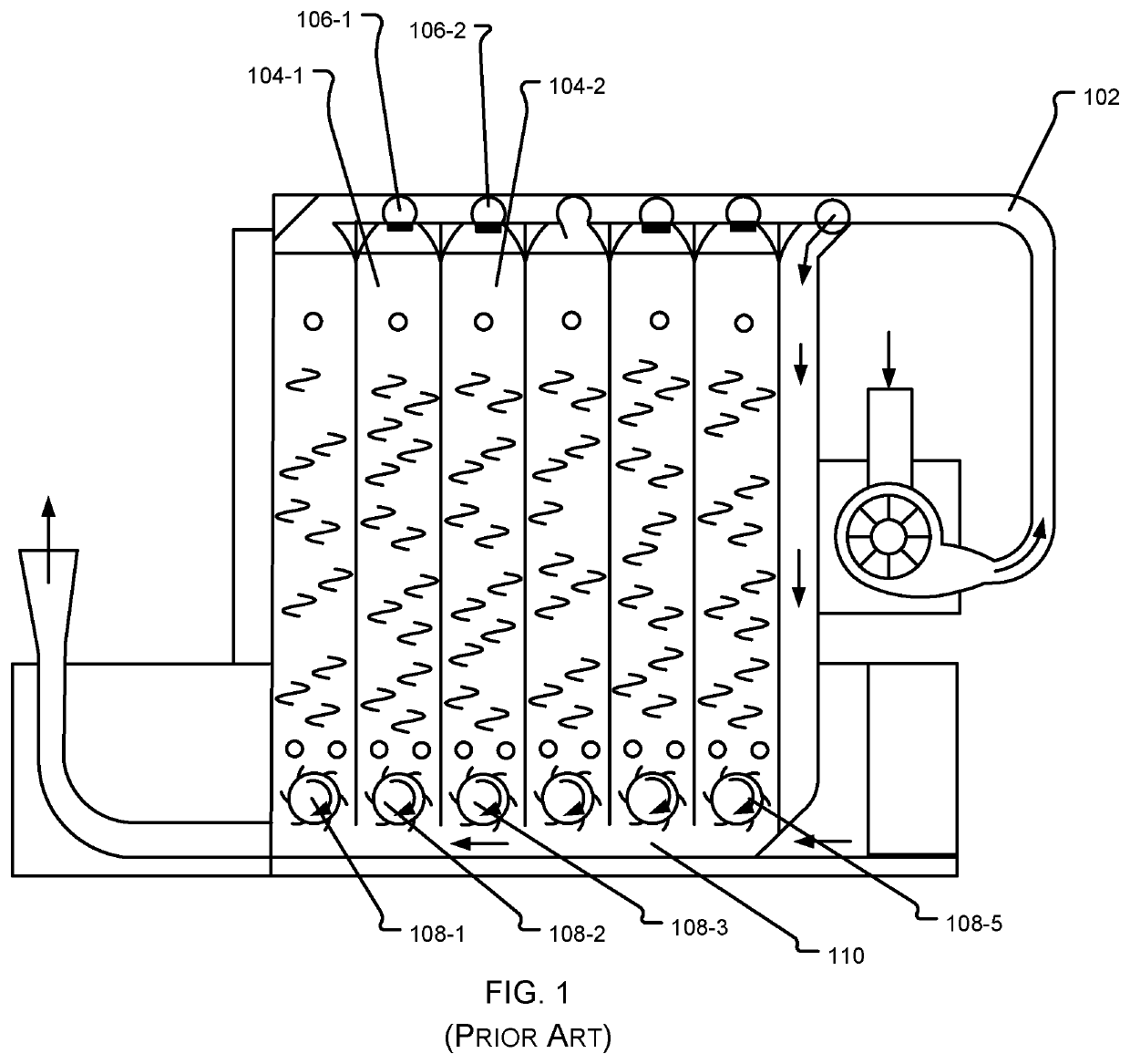
Typically, these machines consist either of spike rollers of varying sizes, or various types of mechanical beaters, which cause a considerable amount of long and good fibbers to break leading to loss in terms of quality of material.
Since the conventional methods for withdrawing fibre material from different chambers depends on spiked rollers, a considerable amount of long and good fibbers break leading to loss in terms of quality of material.
Besides, the conventional process also suffers from other disadvantages.

Method used


Image

  • Method and apparatus for selectively injecting fibre material from multiple chambers into a single chamber
  • Method and apparatus for selectively injecting fibre material from multiple chambers into a single chamber
  • Method and apparatus for selectively injecting fibre material from multiple chambers into a single chamber

Examples


Embodiment Construction

[0036]The following is a detailed description of embodiments of the disclosure depicted in the accompanying drawings. The embodiments are in such detail as to clearly communicate the disclosure. However, the amount of detail offered is not intended to limit the anticipated variations of embodiments; on the contrary, the intention is to cover all modifications, equivalents, and alternatives falling within the spirit and scope of the present disclosure as defined by the appended claims.

[0037]Each of the appended claims defines a separate invention, which for infringement purposes is recognized as including equivalents to the various elements or limitations specified in the claims. Depending on the context, all references below to the “invention” may in some cases refer to certain specific embodiments only. In other cases it will be recognized that references to the “invention” will refer to subject matter recited in one or more, but not necessarily all, of the claims.

[0038]Various ter...


PUM

PropertyMeasurementUnit
Ratioaaaaaaaaaa
Shapeaaaaaaaaaa
Frequencyaaaaaaaaaa

Abstract

An apparatus 200 and method for selectively injecting fibre material from multiple chambers into a single chamber in blow room of a spinning facility is disclosed, which use short duration bursts of pressurized gaseous fluid from nozzles 208 located adjacent to openings 206 provided in each of the plurality of chambers 202, each chamber 202 holding a different type / batch of fibre material, to evacuate predetermined quantities of fibre materials from different chambers 202, and eject the evacuated material into a mixing chamber 204. Duration / frequency of the short duration bursts is controlled to evacuate the predetermined quantities from different chambers. The bursts of the pressurized gaseous fluid also enable opening of the fibre material and spreading the opened fibres in to the mixing chamber 204 resulting in cleaning and better mixing of the fibres.

Description

TECHNICAL FIELD[0001]The present disclosure relates to the field of textile machinery. in particular, the present disclosure relates to machines used in blow room of a spinning facility. more particularly, it pertains to a method and apparatus for selectively injecting fibre material from multiple chambers into a single chamber.BACKGROUND[0002]Background description includes information that may be useful in understanding the present invention. It is not an admission that any of the information provided herein is prior art or relevant to the presently claimed invention, or that any publication specifically or implicitly referenced is prior art.[0003]Machines used in blow rooms of spinning facilities are well known in the art. When bales of fibre material, manmade or artificial, arrive at a spinning mill, these are subjected to various operations in the blow room to make the material suitable for spinning. As a general rule, operations in a blow room comprise: opening the bale, clean...

Claims


Application Information

Patent Timeline
IPC IPC(8): D01G13/00D01G23/04D01G23/08
CPCD01G13/00D01G23/08D01G23/04
Inventor SUTARIA, TARANG J
Owner SUTARIA TARANG J
Learn More