Hinge for load transport trolleys

Pending Publication Date: 2021-09-09
HILTI AG
View PDF0 Cites 0 Cited by
  • Summary
  • Abstract
  • Description
  • Claims
  • Application Information

AI Technical Summary

Benefits of technology

[0016]According to a further advantageous embodiment, it can be possible that a spring element, which is designed as a compression spring, is provided between the clamping lever and the first connecting element, with the result that the clamping lever can be moved from the released position counter to a spring force of the spring element into the clamped position. The movement of the clamping lever from a clamped position into a released position can be facilitated by the e

Problems solved by technology

Rigid and immovable shelves on load transport trolleys can constitute a problem w

Method used


Image

  • Hinge for load transport trolleys
  • Hinge for load transport trolleys
  • Hinge for load transport trolleys

Examples


Example

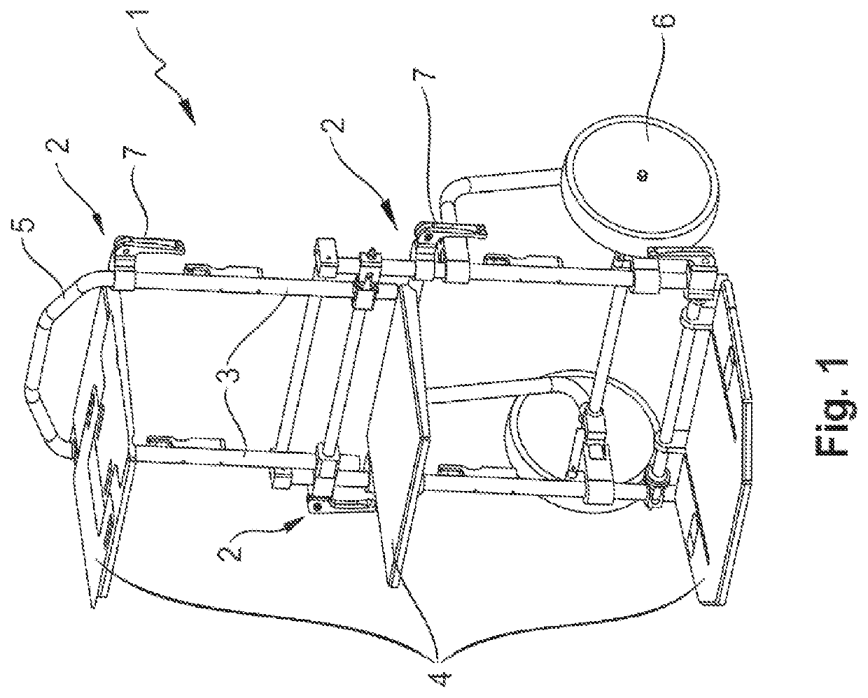
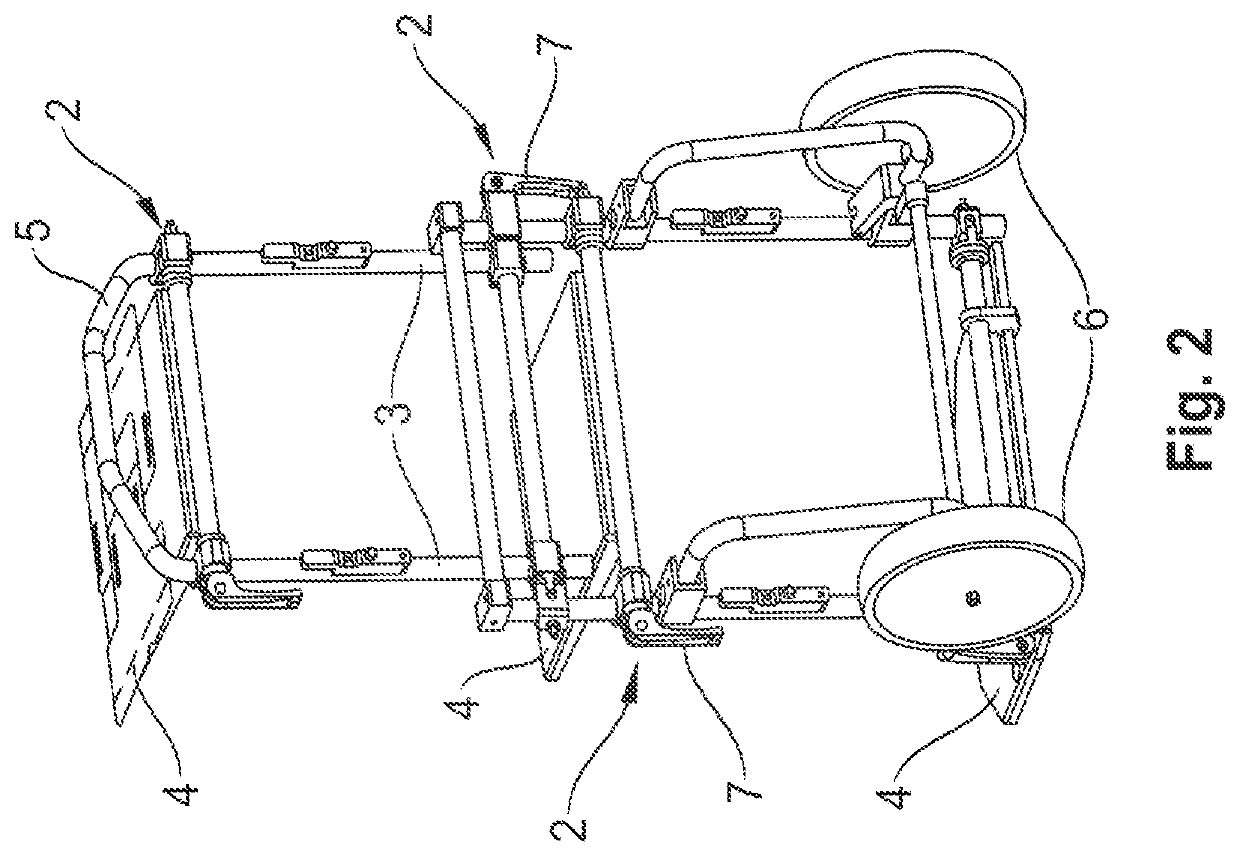
[0051]FIGS. 1 and 2 show a load transport trolley 1 having a clamping device 2 according to invention. The load transport trolley 1 serves for transporting loads, preferably toolboxes. The load transport trolley 1 substantially comprises a tubular frame 3, three shelves 4, a handle 5, two wheels 6 and the clamping device 2. It is possible here that the load transport trolley 1 comprises more or fewer than three shelves 4. A clamping device 2 can be provided for each shelf 4 in order to fix or position the shelf 4 in any desired position or orientation according to the invention.

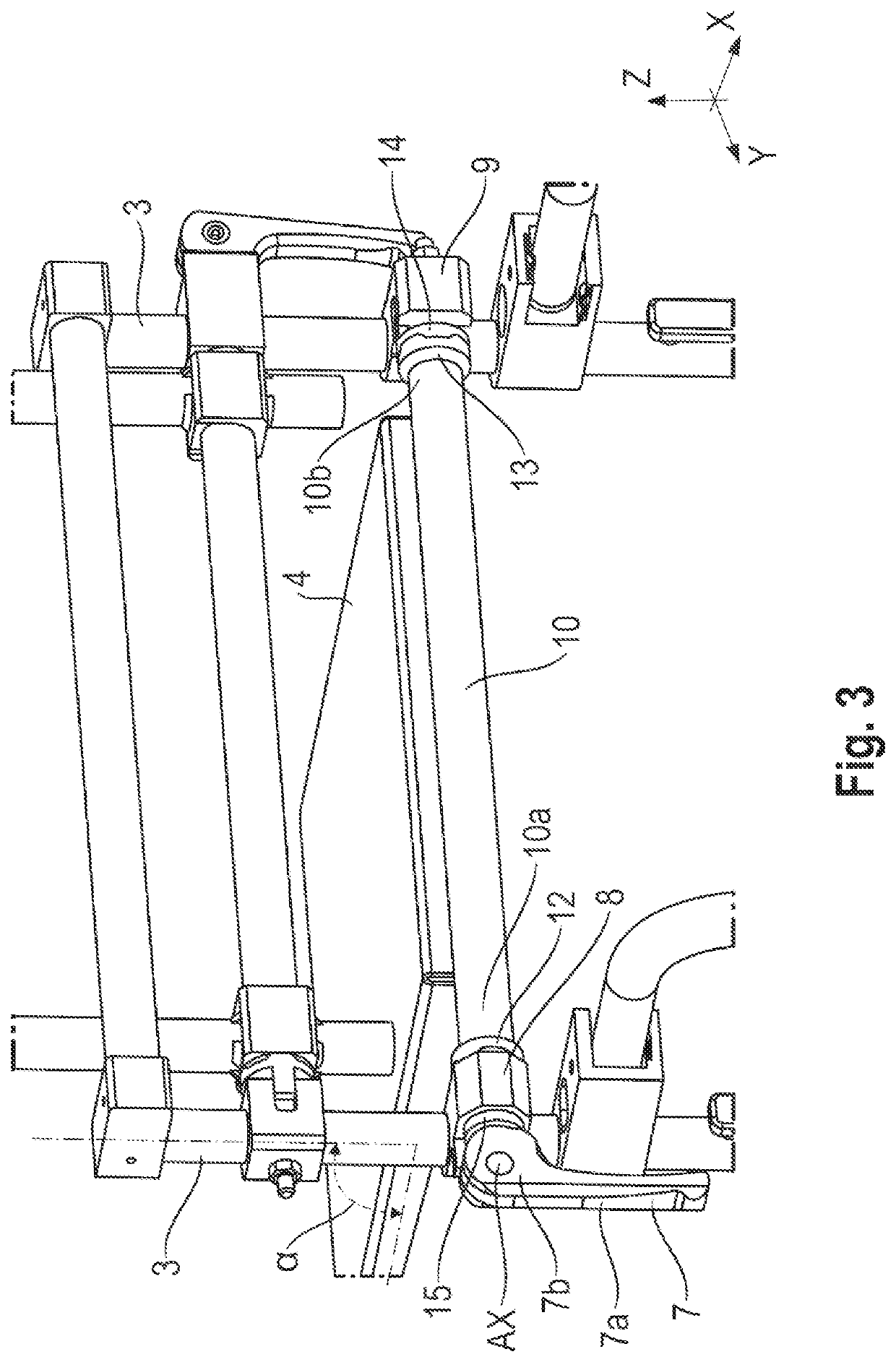
[0052]As illustrated in FIG. 3, the clamping device 2 substantially comprises a clamping lever 7, an axle 8 of the clamping lever 7, a first connecting element 8, a second connecting element 9, an attachment element 10, a pull rod 11 (see, e.g., FIG. 13), a first positioning element 12, a second positioning element 13, a blocking element 14, a stop element 15 and a spring element 16 (see, e.g., FIG. 13).

[0053...


PUM


Abstract

Clamping device for variably positioning an angular setting of at least one shelf on a load transport trolley for transporting loads, preferably toolboxes. The clamping device includes a clamping lever for reversibly setting the clamping device in a clamped or released position, wherein, in the released position, the shelf is moveable; a pull rod which can be reversibly moved by the clamping lever into a first or second position, wherein the clamping device is in the clamped position when the pull rod is set into the first position, and the clamping device is in the released position when the pull rod is set into the second position; an attachment element for connecting the shelf to the clamping device; and a first and second connecting element for connecting the clamping device to a frame of the load transport trolley.

Description

[0001]The present invention relates to a clamping device for variably positioning an angular setting of at least one shelf on a load transport trolley for transporting loads, preferably toolboxes.BACKGROUND[0002]Load transport trolleys of the type mentioned at the beginning are known in principle from the prior art, for example in the form of handcarts. Such load transport trolleys can have one or more shelves which serve to receive or bear loads. It is customary for said shelves to be rigidly and immovably fastened to the load transport trolley.SUMMARY OF THE INVENTION[0003]Rigid and immovable shelves on load transport trolleys can constitute a problem when the load transport trolley is intended to be stowed in a space-saving manner.[0004]It is an object of the present invention to solve the aforementioned problem and in particular to provide a load transport trolley for transporting loads, preferably toolboxes, with said trolley being able to be stowed in a space-saving manner.[00...

Claims


Application Information

Patent Timeline
IPC IPC(8): F16B2/18
CPCF16B2/185B62B1/12B62B2205/33B25H3/00
Inventor KARLSSON, KENTH
Owner HILTI AG
Why Eureka
Try Eureka