Eureka AIR delivers breakthrough ideas for toughest innovation challenges, trusted by R&D personnel around the world.

Grinding method

Active Publication Date: 2021-09-23
DISCO CORP
View PDF0 Cites 0 Cited by
  • Summary
  • Abstract
  • Description
  • Claims
  • Application Information

AI Technical Summary

Benefits of technology

The present invention relates to a grinding device that prevents chippings from being formed on the reverse side of a ring-shaped stiffening portion during grinding. This is achieved by rotating the grinding wheel about a central axis of a second rotational shaft that is tilted with respect to a first rotational shaft, and then forming a ring-shaped recess in the reverse side of the workpiece by grinding the central portion of the reverse side. This reduces the number of chippings that may be formed on the reverse side of the ring-shaped stiffening portion.

Problems solved by technology

However, in the grinding step, a number of chippings tend to be produced on the reverse side of the ring-shaped stiffening portion, lowering its own mechanical strength, due to an impact of grindstones contacting the reverse side of a workpiece and outer side faces of the grindstones contacting an inner circumferential side face of the ring-shaped stiffening portion.
Furthermore, in a case where the workpiece is processed by wet etching after the grinding step, the areas of the ring-shaped stiffening portion where the chippings have been formed are etched, forming surface irregularities on the reverse side of the ring-shaped stiffening portion.
The surface irregularities thus formed are likely to cause other problems in subsequent processes.
For example, a metal film evaporated on the reverse side of the ring-shaped stiffening portion is liable to be peeled off from the surface irregularities that act as peel initiating points.
Moreover, when a dicing tape is affixed to the reverse side of the workpiece, the dicing tape is likely to fail to be affixed properly to the workpiece on account of the surface irregularities.

Method used


Image

  • Grinding method
  • Grinding method
  • Grinding method

Examples


Embodiment Construction

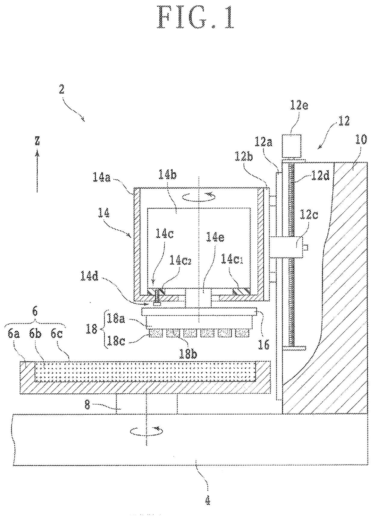
[0018]A grinding method according to an embodiment of the present invention will be described in detail below with reference to the accompanying drawings. First, a grinding apparatus 2 on which the grinding method is carried out will be described below with reference to FIG. 1. FIG. 1 is a side elevational view, partly in cross section, of the grinding apparatus 2. As illustrated in FIG. 1, the grinding apparatus 2 has a base 4 substantially in the form of a rectangular parallelepiped supporting a plurality of components of the grinding apparatus 2 thereon. A disk-shaped chuck table 6 is rotatably mounted on the base 4. The chuck table 6 has a frame 6a made of ceramic that has a fluid channel, not illustrated, defined therein. The fluid channel has an end connected to a suction source, not illustrated, such as an ejector.

[0019]The frame 6a has a recess defined as a disk-shaped space in an upper surface thereof. A disk-shaped porous plate 6b is fixedly disposed in the recess. Note th...


PUM


Abstract

A grinding method includes an oblique grinding step of rotating a grinding wheel about the central axis of a second shaft, tilting the second shaft to a first shaft of a rotatable chuck table such that the bottom of a first portion of the grinding wheel that is positioned above an outer circumferential portion of the chuck table is higher than the bottom of a second portion of the grinding wheel that is positioned above a central portion of the chuck table, and then moving the grinding wheel and the chuck table relatively closer to each other along a direction parallel to the first shaft, thereby forming a disk-shaped recess in the reverse side of the workpiece, and a tilt changing and grinding step of grinding the reverse side of the workpiece while gradually changing a tilt of the second shaft to orient parallel to the first shaft.

Description

BACKGROUND OF THE INVENTIONField of the Invention[0001]The present invention relates to a grinding method for grinding a central portion of a reverse side of a workpiece to form in the reverse side of the workpiece a disk-shaped recess including a circular portion that has been ground and a ring-shaped stiffening portion that has been unground which surrounds the periphery of the circular ground portion.Description of the Related Art[0002]Workpieces having a plurality of areas demarcated on a face side thereof by a grid of projected dicing lines and a plurality of devices such as integrated circuits (ICs), or large-scale-integration (LSI) circuits formed in the respective areas are divided into a plurality of device chips by a grinding step, a cutting process, and so on. One method of grinding a workpiece grinds only a circular central portion of the reverse side of the workpiece that is aligned thicknesswise across the workpiece with a circular device region of the face side of the...

Claims


Application Information

Patent Timeline
IPC IPC(8): B24B41/04B24B1/00
CPCB24B41/04B24B1/00B24B41/061B24B37/042B24B37/10B24B7/228H01L21/304
Inventor SUZUKI, YOSHIKAZU
Owner DISCO CORP
Why Eureka
Eureka Blog
Learn More