Self leveling coating system

Active Publication Date: 2021-09-30
O R LASERTECH
View PDF0 Cites 0 Cited by
  • Summary
  • Abstract
  • Description
  • Claims
  • Application Information

AI Technical Summary

Benefits of technology

The patent describes a solution for addressing topography issues in additive manufacturing. The solution compensates for variations in topography that occur in multiple directions, resulting in a more level and complete build platform for object manufacture. By measuring the topography of the build platform and adjusting the inclination of the coater's rake, the selective melting apparatus can deposit material at different rates and fuse it after each deposition, approaching the desired build platform profile over multiple passes of the coater. The technical effect of the patent is a more accurate and effective solution for additive manufacturing with complex build platform topography.

Problems solved by technology

Known solutions fail to address topography issues of build platforms in additive manufacturing.
First, known solutions do not accurately position the coater above the platform.
This can lead to multiple deficiencies in the initial layers, such as layers that are too thick and thus not fully melted or sintered when irradiated by the laser.
Second, known solutions can address a sloped topography, but cannot compensate for topographies that vary in multiple directions.
For example, if a build platform topography includes parallel ridges and valleys, then known solutions cannot deposit the material selectively such that more material is added and fused in the troughs (thereby “filling” the troughs).
Further, if the ridges and valleys have different heights (for example, with an irregular topography), then known solutions fail because they cannot vary material addition in multiple directions to account for the irregular topography.
Typically, the desired build platform is planar, but without compensation for variations in the multiple directions, the build platform cannot be easily leveled which may result in incomplete fusing of the object.

Method used


Image

  • Self leveling coating system
  • Self leveling coating system
  • Self leveling coating system

Examples


Embodiment Construction

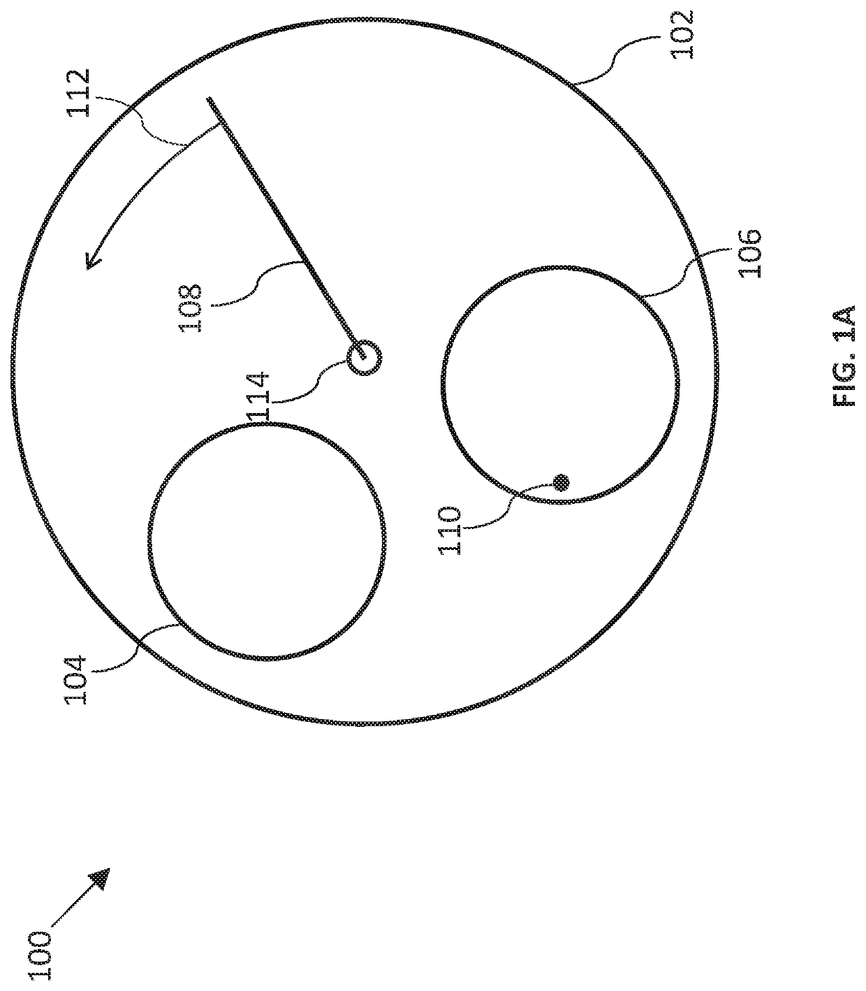
[0025]Turning now to the drawings, wherein like features are designated by like reference numerals, FIG. 1A is a plan-view schematically illustrating an additive manufacturing apparatus 100 in accordance with an embodiment. Apparatus 100 includes build table 102, material source 104, build platform 106, coater 108, and a laser source (not shown) providing a laser beam focused to an irradiation spot 110. Coater 108 follows arcuate path 112 over build table 102 (from material source 104 to build platform 106) by rotating about axis 114 (which extends out of the page). Coater 108 moves in a plane of motion (not shown) which includes arcuate path 112. Coater 108 may include any of the coaters described herein, including coater 300, coater 502, and coater 602.

[0026]Material source 104 provides a material to be spread across build platform 106. The material may comprise a powder (or other flowable substance) which is deposited on build platform 106 by coater 108. The deposited material co...


PUM

PropertyMeasurementUnit
Volumeaaaaaaaaaa
Distanceaaaaaaaaaa

Abstract

Additive manufacturing apparatuses and methods are provided. A coater having a rake moves above a build platform. A sensor measures topography of the build platform. A rake control unit receives the topography, determines (based on the topography) an adjustment of the rake's inclination relative to a reference plane as the coater moves from a first position above the platform to a second position above the platform, and sends command signals to a motor based on the adjustment. The motor adjusts an inclination of the rake relative to the reference plane as the coater moves from the first position to the second position.

Description

TECHNICAL FIELD OF THE INVENTION[0001]The present disclosure relates generally to additive manufacturing and, in particular, to levelling a build platform in a three-dimensional laser printing process.DISCUSSION OF BACKGROUND ART[0002]Additive manufacturing, a three-dimensional (“3-D”) printing technique, involves depositing material and laser-irradiating the material to form a desired object. Material is deposited in layers, and the laser irradiates the material layer-by-layer to build cross-sections of the object according to a 3-D model. Non-irradiated material is removed (for example, material is removed between layers or after all layers of the object are formed) to produce the 3-D object. Two examples of additive manufacturing include laser selective sintering and laser selective melting.[0003]Additive manufacturing apparatuses can include four main components: a material source, a coater, a build platform, and a laser. The object is built layer-by-layer on the build platform....

Claims


Application Information

Patent Timeline
IPC IPC(8): B29C64/214B29C64/153B29C64/393B33Y10/00B33Y30/00B33Y50/02
CPCB29C64/214B29C64/153B33Y50/02B33Y10/00B33Y30/00B29C64/393B22F10/28B22F12/67B22F12/90B22F10/37B22F2999/00B22F12/224B22F12/226B22F12/222
Inventor WOLF, MARKUS
Owner O R LASERTECH
Why Eureka
Try Eureka