
Threshing Device with Two-Way Pull Wires and Adjustable Threshing Clearance and Combined Harvester

a threshing device and threshing clearance technology, which is applied in the field of agricultural machinery, can solve the problems of time-consuming and laborious, failure to realize automatic adjustment, and threshing drum clogging in the actual operation of the combined harvester, and achieves low level of automation, easy operation, and easy realization of automatic adjustment

Active Publication Date: 2021-10-28
JIANGSU UNIV
View PDF0 Cites 0 Cited by
  • Summary
  • Abstract
  • Description
  • Claims
  • Application Information

AI Technical Summary

Benefits of technology

The present invention is a threshing device with two-way pull wires and adjustable threshing clearance. It solves the problem of clogging in the combined harvester by adjusting the position of the grid bars through a tangential tensioning device and a radial tensioning device. This allows for separate adjustment of the grid bars, synchronized adjustment in the circumferential direction, and effective stabilization of the grid bars during the threshing process. A guide device ensures successful turning of the radial pull wires and simultaneous adjustment of the grid bars. The adjusting mechanism is conveniently arranged and prevents interference with the working area of the concave plate.

Problems solved by technology

Failures such as threshing drum clogging may occur in the actual operation of a combined harvester, owing to excessive feed amount or sudden change of feed amount incurred by different cereal planting conditions and different field conditions, etc.
Generally, a traditional solution is to shut down the combined harvester and replace the concave plate or adjust the concave clearance, which is time-consuming and labor-intensive.
The invention can be used for detecting stress on the threshing rack bars of the threshing and separating unit and adaptively adjusting the concave clearance of a combined harvester during field harvesting, but the adjustment method is designed for a threshing device in which the threshing rack bars have spike teeth, and is limited in applicability; moreover, the adjustment method is to increase the threshing clearance by rotating one side of the concave plate, which may result in inconsistent concave clearance in the circumferential direction of the drum after the adjustment; if the rotation angle is too great, it may result in under-threshing owing to excessive threshing clearance; if the rotation angle is too small, it may result in clogging on one side of the drum, and may lead to new problems.
The adjusting device for a concave clearance comprises an actuating mechanism and a reversing mechanism, wherein the actuating mechanism reciprocates in a preset direction and controls a moving concave plate arranged around the drum to move toward or away from the drum, the reversing mechanism is connected to the actuating mechanism and the moving concave plate respectively, so that the movement direction of the moving concave plate is at a first preset angle from the movement direction of the actuating mechanism, and the concave clearance can be adjusted freely, however, the mechanisms are relatively complex and difficult to arrange; moreover, it is unable to uniformly enlarge the threshing clearance by moving the entire concave plate toward or away from the drum to adjust the threshing clearance; consequently, there may be problems that the clearance at the bottom of the drum may be too large while the clearance at both sides of the drum may be too small, or that the clearance at the bottom may be too small while the clearance at both sides may be too large.
However, four hydraulic oil cylinders used for adjustment may be non-synchronous in the process of adjustment, since the adjusting devices are arranged at four corners of the concave plate; consequently, the threshing clearance adjustment may be unsuccessful.
In addition, since great force is required to move the entire concave plate, the energy consumption may be increased.
The integral adjustment of the concave plate may also result in non-uniform threshing clearance after the adjustment, which may have impact on the normal operation of the combined harvester.
However, with such a method, a large number of sensors are required for data acquisition, and several hydraulic oil cylinders are required to work cooperatively, and a large amount of pipelines and cables are required.
Therefore, it is inapplicable to the actual operation process of a combined harvester.
However, the driving mechanism with the pull rod adjustment method is relatively complex, and is inconvenient to implement.
The synchronous up-down adjustment of both sides usually relies on a plurality of hydraulic cylinders to realize the adjustment of the concave plate, which is relatively difficult to implement, and cannot realize fine adjustment.
In addition, it is unable to uniformly enlarge the threshing clearance by moving the entire concave plate toward or away from the drum to adjust the threshing clearance; consequently, there may be problems that the clearance at the bottom of the drum may be too great while the clearance at both sides may be too small, or that the clearance at the bottom may be too small while the clearance at both sides may be too large.
However, the driving mechanism is relatively complex, the adjustment is not convenient enough, and the of the concave clearance is inconsistent in the circumferential direction of the drum after adjustment; in addition, if the rotation angle is too great, it may result in under-threshing owing to excessive clearance; if the rotation angle is too small, it may result in clogging on one side of the drum, and may lead to new problems.
Moreover, the adjustment method is not adaptive to different working conditions, and may affect the threshing performance.

Method used


Image

  • Threshing Device with Two-Way Pull Wires and Adjustable Threshing Clearance and Combined Harvester
  • Threshing Device with Two-Way Pull Wires and Adjustable Threshing Clearance and Combined Harvester
  • Threshing Device with Two-Way Pull Wires and Adjustable Threshing Clearance and Combined Harvester

Examples


embodiment 1

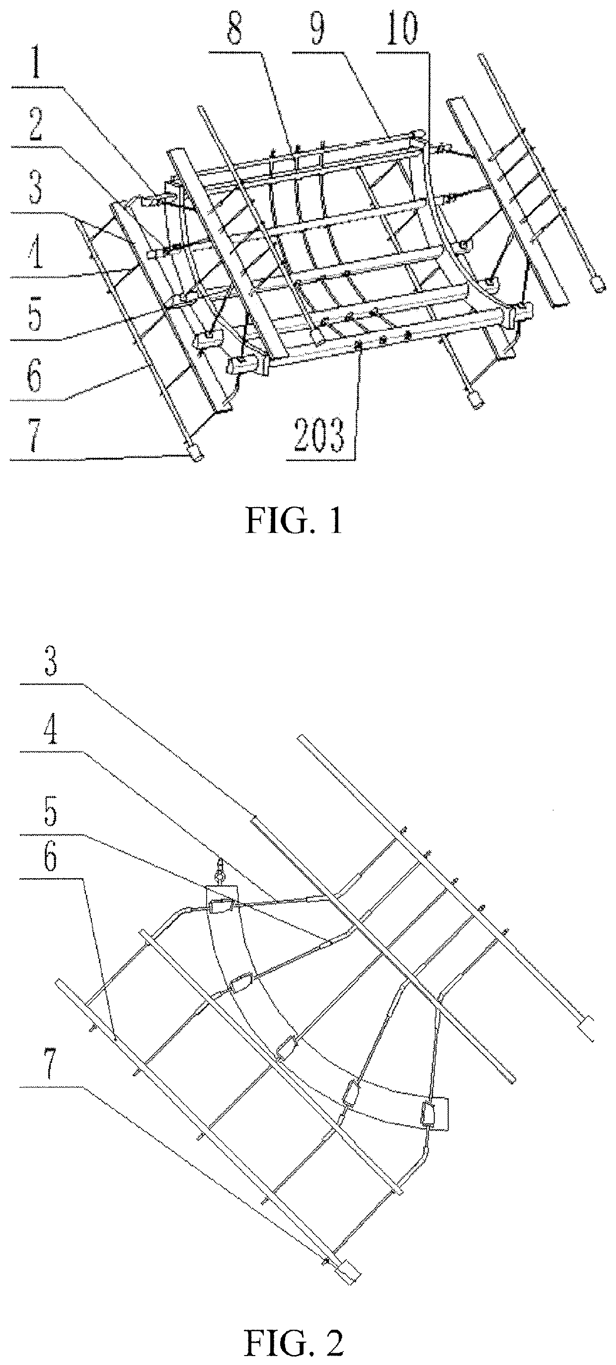
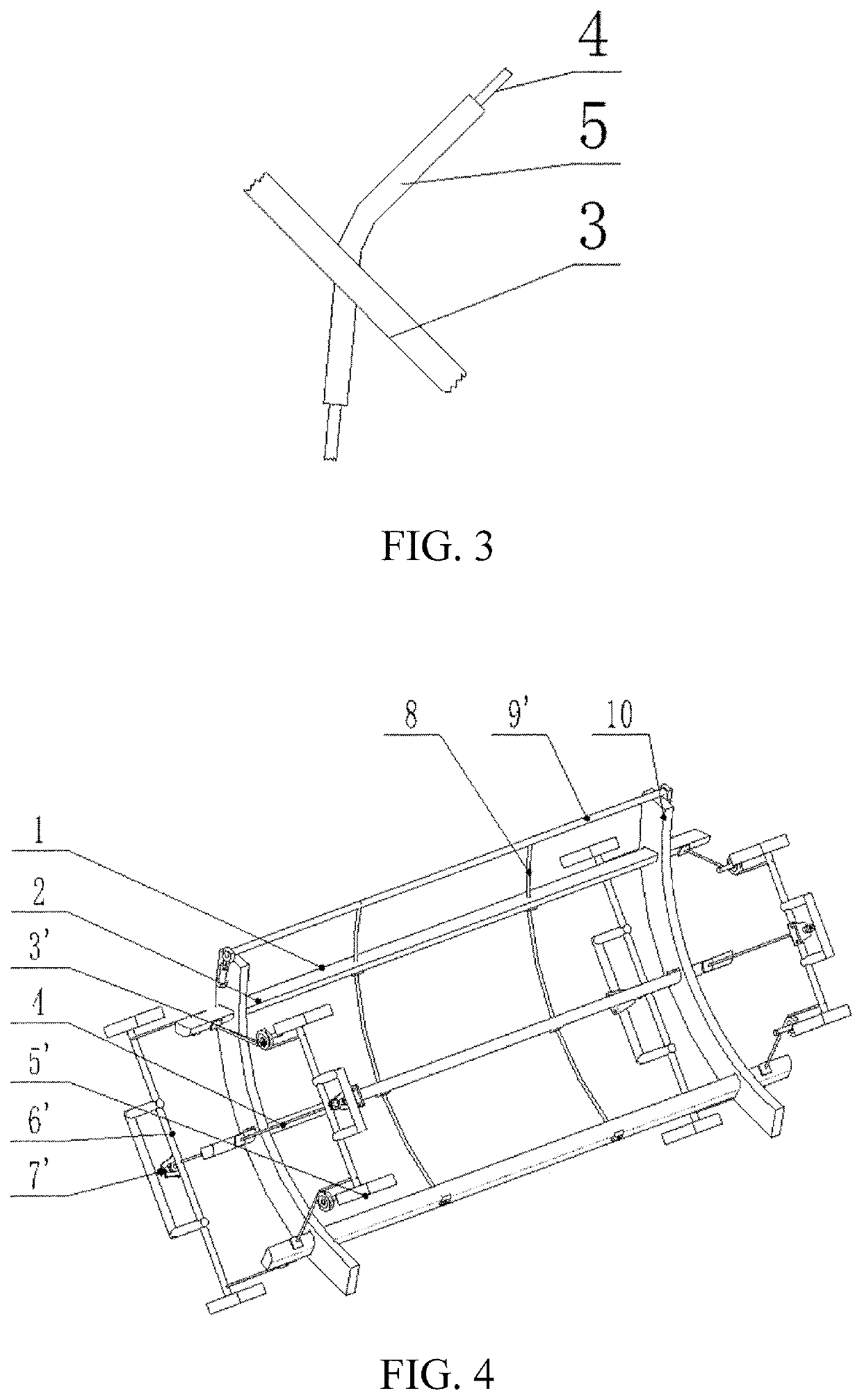
[0041]An existing grid concave plate includes grid bars 1 and side plates 10. As the structure belongs to the prior art, the specific structure of the grid concave plate is not described. In an embodiment 1 as shown in FIGS. 1 and 2, the threshing device with two-way pull wires and adjustable threshing clearance according to the present invention includes a tensioning mechanism, which includes elastic gaskets 2, a fixing plate 3, radial pull wires 4, guide sleeves 5, a rotating shaft A 6, an electric motor 7, tangential pull wires 8, and a rotating shaft B 9. The grid bars 1 are mounted in holes of the side plates 10, and have certain clearance in the radial and tangential directions, so that the grid bars 1 can be moved in the radial direction and thereby the threshing clearance can be adjusted. The size of the radial clearance is determined according to the clearance required in the threshing process. There are holes in the radial direction on both sides of each grid bar and sever...

embodiment 2

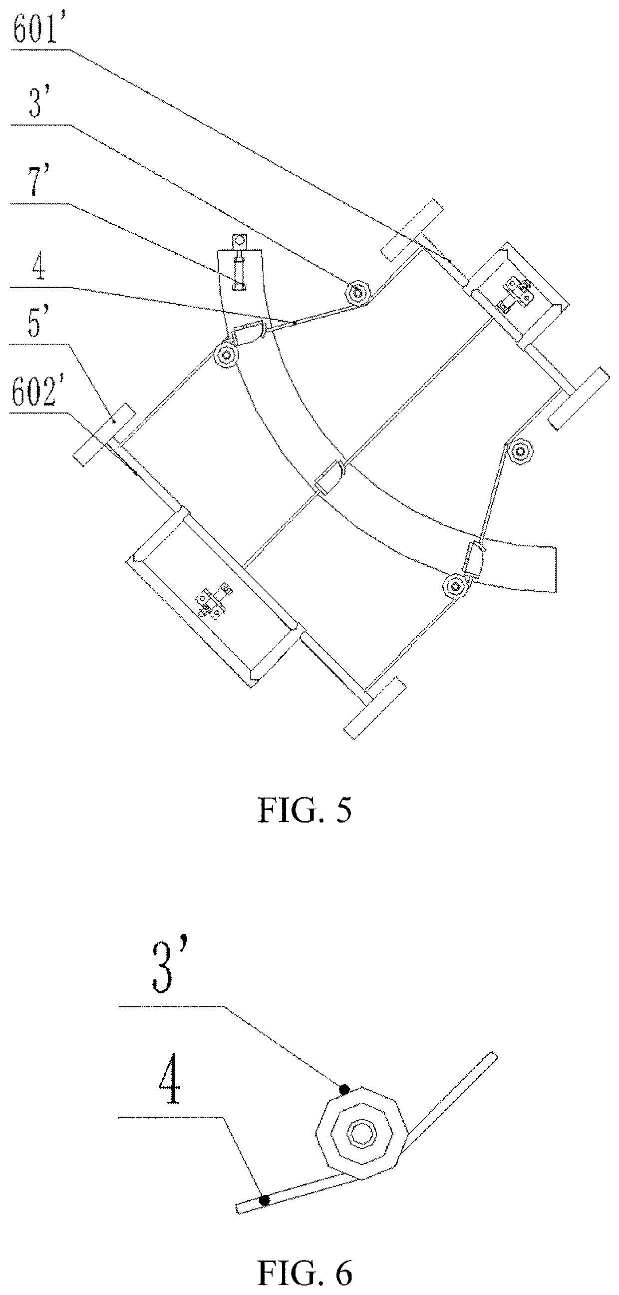
[0046]In an embodiment 2 as shown in FIGS. 4, 5 and 7, the threshing device with two-way pull wires and adjustable threshing clearance according to the present invention includes a tensioning mechanism, which includes elastic gaskets 2, guide pulleys 3′, radial pull wires 4, a slide channel 5′, a pull rod A 6′, an electric push rod 7′, tangential pull wires 8, and a pull rod B 9′. The grid bars 1 are mounted in the holes of the side plates 10, and have certain clearance in the radial and tangential directions, so that the grid bars 1 can be moved in the radial direction and thereby the threshing clearance can be adjusted. There are holes in the radial direction on both sides of each grid bar and several holes evenly distributed in the tangential direction in the middle part. An upper pull rod A 601′ and a lower pull rod A 602′ are arranged on two side edges of the concave plate and in the radial direction of the grid bars 1, one end of the radial pull wire 4 passes through a radial ...


PUM


Abstract

A threshing device with two-way pull wires and adjustable threshing clearance includes a tensioning mechanism, and several grid bars in clearance fit with side plates, wherein the tensioning mechanism is mounted on the several grid bars so that the grid bars can move in radial and tangential directions in the clearance; the tensioning mechanism includes a tangential tensioning device and a radial tensioning device, wherein the radial tensioning device is mounted in the radial direction of any one of the grid bars, so that the grid bars can move in the radial direction in the clearance; the tangential tensioning device is mounted in series in the tangential direction of the grid bars, so that the grid bars can move in the tangential direction in the clearance. The present invention further provides a combined harvester, which includes the threshing device with two-way pull wires and adjustable threshing clearance. With the combined harvester, the threshing clearance can be adjusted by adjusting the positions of the grid bars according to the actual conditions of harvesting operation. The adjusting mechanism is relatively simple, and can easily realize automatic adjustment and control of the concave clearance.

Description

TECHNICAL FIELD[0001]The present invention relates to the field of agricultural machinery, in particular to a threshing device with two-way pull wires and adjustable threshing clearance and a combined harvester.BACKGROUND ART[0002]The threshing device is one of the core components of a combined harvester, and its main function is to thresh off cereal grains from stalks. The quality of threshing performance has direct influence on the operating efficiency and performance of the combined harvester, and the size of concave clearance also has influence on the quality of grain harvesting to a certain degree. Failures such as threshing drum clogging may occur in the actual operation of a combined harvester, owing to excessive feed amount or sudden change of feed amount incurred by different cereal planting conditions and different field conditions, etc. Generally, a traditional solution is to shut down the combined harvester and replace the concave plate or adjust the concave clearance, w...

Claims


Application Information

Patent Timeline
IPC IPC(8): A01F12/28
CPCA01F12/28A01D41/1274A01D75/182A01F12/181A01F12/24A01F12/26
Inventor MA, ZHENGHAN, MINLI, YAOMINGXU, LIZHANGMA, KECHAOTANG, ZHONGLU, ENLIANG, ZHENWEI
Owner JIANGSU UNIV
Learn More