Check patentability & draft patents in minutes with Patsnap Eureka AI!

Image debanding method

a debanding method and image technology, applied in image enhancement, image analysis, instruments, etc., can solve the problems of large amount of calculation generated, abnormal color gamut boundary of image, and color band often generated on low-capacity images

Active Publication Date: 2021-11-11
REALTEK SEMICON CORP
View PDF10 Cites 2 Cited by
  • Summary
  • Abstract
  • Description
  • Claims
  • Application Information

AI Technical Summary

Benefits of technology

The patent text describes an image debanding method that selects comparison pixels based on their color value and distance from the to-be-compensated pixel. The method calculates compensation values based on differences between the color values of the comparison pixels and the to-be-compensated pixel, and a random number. The results are then used to calculate the post-debanding color component value of the to-be-compensated pixel. The technical effect of this method is a more accurate and precise debanding of images, resulting in improved image quality.

Problems solved by technology

However, due to the reduction of some color details, a color band is often generated on the low-capacity image, that is, the image has an abnormal color gamut boundary.
In this way, a considerable amount of calculation is generated, excessively long calculation time is caused, and excessively calculation resources are consumed.
In addition, the considerable large amount of calculation also increases hardware complexity of the debanding, that is, production costs cannot be reduced.

Method used


Image

  • Image debanding method
  • Image debanding method
  • Image debanding method

Examples


Embodiment Construction

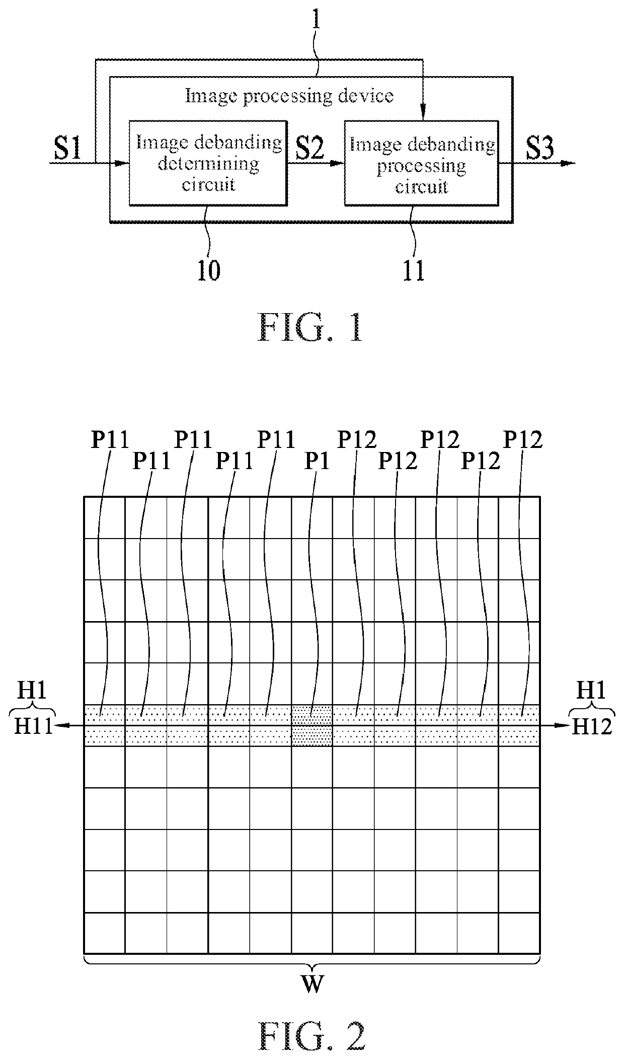
[0013]FIG. 1 is a circuit block diagram according to an embodiment of an image processing device 1 applying an image debanding processing circuit 11 of the present invention. Referring to FIG. 1, the image processing device 1 includes an image debanding determining circuit 10 and an image debanding processing circuit 11 coupled to the image debanding determining circuit 10. The image debanding determining circuit 10 may receive an input image signal S1, and determine whether a plurality of pixels of the input image signal S1 is debanding-required to generate a determining result S2. If the determining result S2 indicates that any pixel of the input image signal S1 may require to be debanded, the image debanding processing circuit 11 performs the debanding on said pixels. In some embodiments, if the image debanding determining circuit 10 determines that a distance between some pixels of the input image signal S1 and an image boundary is less than a preset distance, a determining resu...


PUM


Abstract

An image debanding method includes selecting a first and a second comparison pixel from a plurality of adjacent pixels within a preset pixel distance range in a straight pixel direction according to each of the plurality of adjacent pixels and the to-be-compensated pixel; calculating a first compensation value according to a first difference between pre-debanding color values of the first comparison pixel and the to-be-compensated pixel, a first pixel distance between the first comparison pixel and the to-be-compensated pixel, and the preset pixel distance range; calculating a second compensation value according to a second difference between the pre-debanding color values of the second comparison pixel and the to-be-compensated pixel, a second pixel distance between the second comparison pixel and the to-be-compensated pixel, and the preset pixel distance range; and calculating a post-debanding color component value of the to-be-compensated pixel.

Description

CROSS-REFERENCE TO RELATED APPLICATION[0001]This non-provisional application claims priority under 35 U.S.C. § 119(a) to patent application Ser. No. 10 / 911,4948 in Taiwan, R.O.C. on May 5, 2020, the entire contents of which are hereby incorporated by reference.BACKGROUNDTechnical Field[0002]The present invention relates to an image debanding method.Related Art[0003]In a conventional image processing technology, in order to produce a low-capacity image, some color details are often omitted in quantization and encoding programs of image processing, or the image is compressed to produce a low-capacity image. However, due to the reduction of some color details, a color band is often generated on the low-capacity image, that is, the image has an abnormal color gamut boundary. Therefore, the color band of the image needs to be eliminated to improve image definition. In a conventional color band elimination technology, if debanding is to be performed on one of pixels, pixels of the entire ...

Claims


Application Information

Patent Timeline
IPC IPC(8): G06T5/00G06T7/90
CPCG06T5/002G06T2207/10024G06T7/90G06T5/20H04N19/86H04N1/64G06T5/70
Inventor LEE, KUNG-HO
Owner REALTEK SEMICON CORP
Features
  • R&D
  • Intellectual Property
  • Life Sciences
  • Materials
  • Tech Scout
  • Unparalleled Data Quality
  • Higher Quality Content
  • 60% Fewer Hallucinations
Learn More