
Input device and image forming apparatus

a technology of input device and image forming apparatus, which is applied in the direction of printing, instruments, optics, etc., can solve the problem that the user cannot feel a physical sense of pushing down, and achieve the effect of suppressing interference with peripheral equipment and suppressing erroneous pulling ou

Active Publication Date: 2021-11-18
CANON KK
View PDF0 Cites 1 Cited by
  • Summary
  • Abstract
  • Description
  • Claims
  • Application Information

AI Technical Summary

Benefits of technology

The present invention is about a new input device for external attachment that can be connected to an image forming apparatus through a cable. One technical effect of this invention is that it prevents interference with the peripheral equipment caused by exposure of the cable to the outside. Another effect is that it prevents errors caused by the user accidentally pulling out the cable.

Problems solved by technology

However, when the input is carried out on the touch panel for receiving the numerical value input by the touch operation, the user cannot feel a physical sense of pushing-down.

Method used


Image

  • Input device and image forming apparatus
  • Input device and image forming apparatus
  • Input device and image forming apparatus

Examples


Embodiment Construction

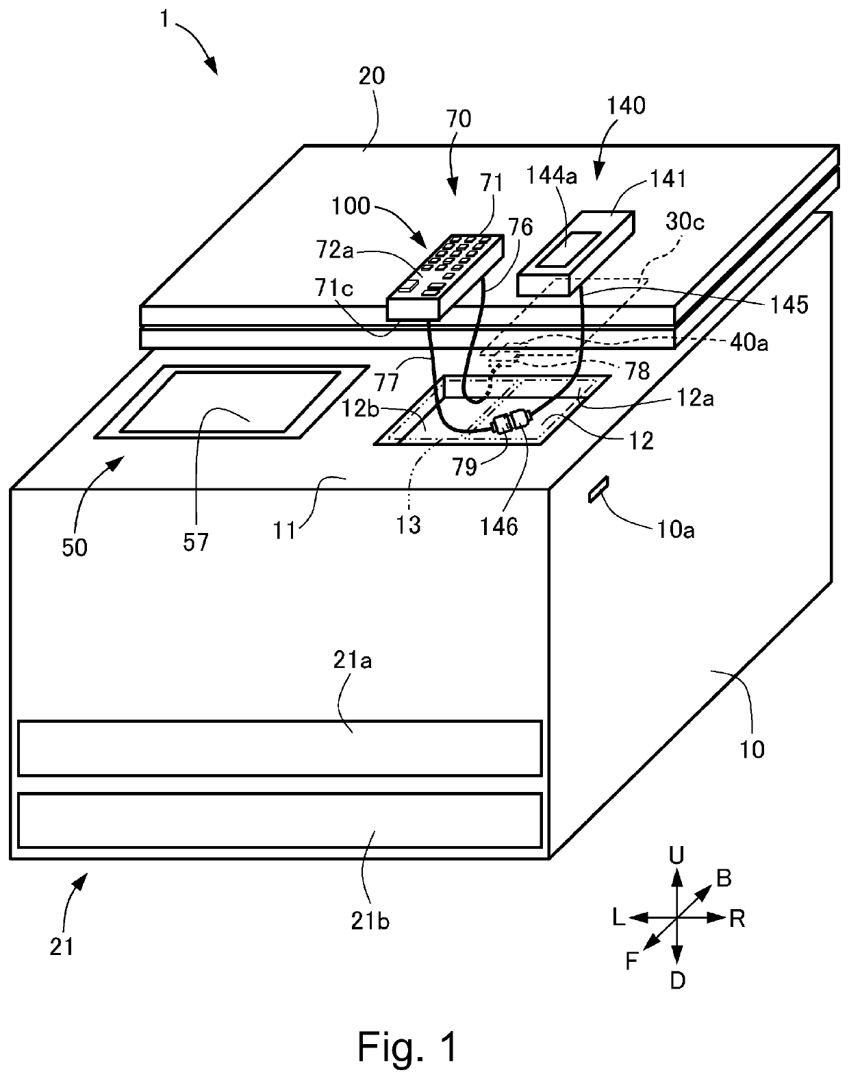
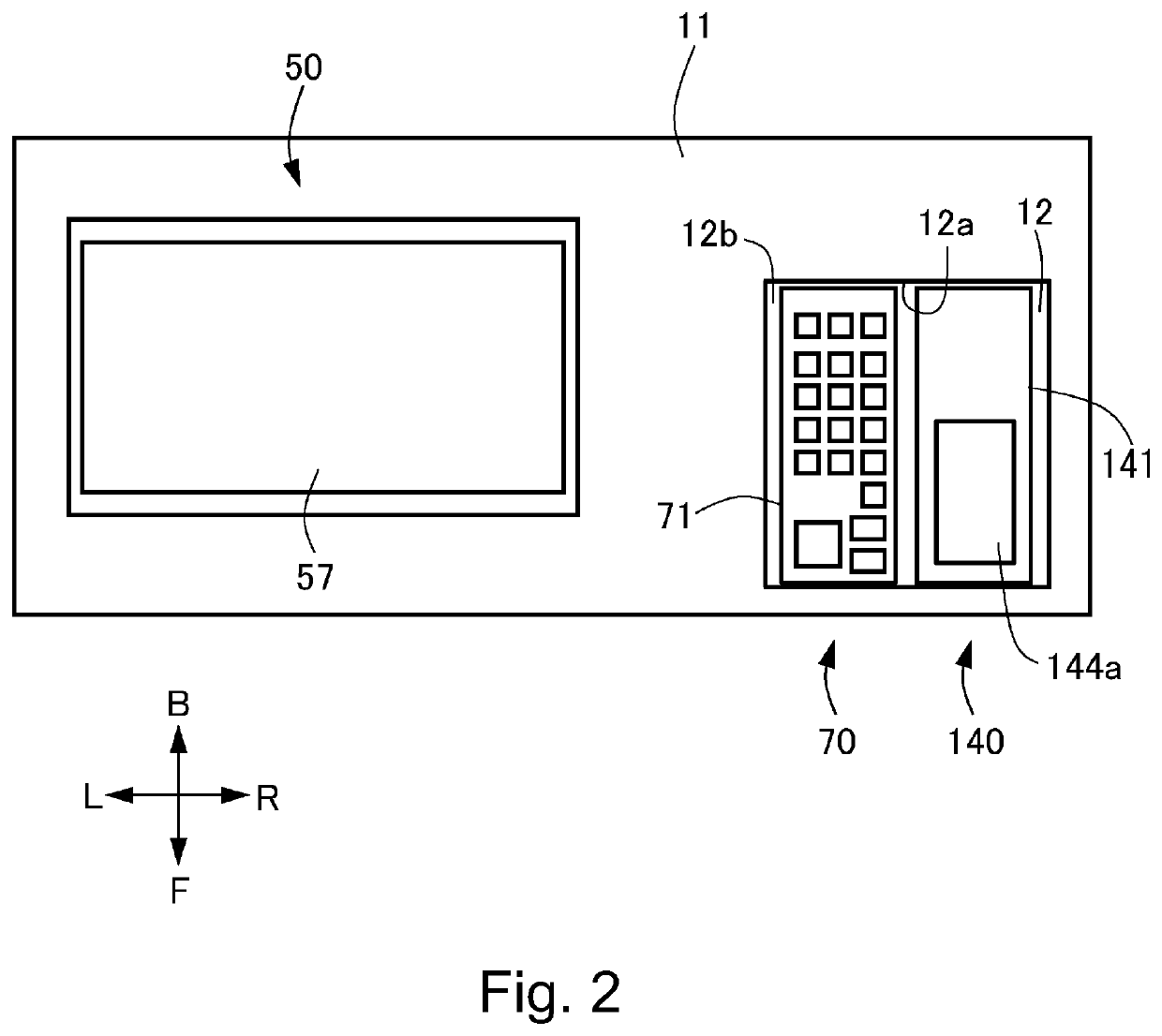
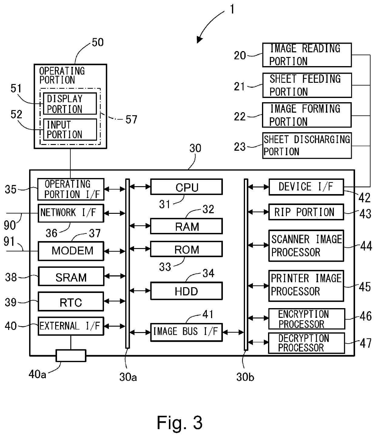
[0019]In the following, an embodiment of the present invention will be specifically described with reference to FIGS. 1 to 8. Incidentally, in this embodiment, as shown in each of the figures, toward an image forming apparatus 1, a front side is represented by a front side F, a rear side (rear) is represented by a back side B, a left(-hand) side is represented by L, a right(-hand) side is represented by R, an upper (upward) side is represented by U, and a lower (downward) side is represented by D. Further, the image forming apparatus 1 is constituted so that a user is located to face from the front side F toward the back side B and performs various operations. As shown in FIG. 1, in this embodiment, a side where an operating portion 50 described later is provided is the front side F of the image forming apparatus 1.

[0020]In this embodiment, as an example of the image forming apparatus 1, a full-color printer of a tandem type is described. However, the present invention is not limite...


PUM


Abstract

A numerical key unit 70 mounted in a mounting portion 12 of an image forming apparatus 1 and card reader of inputting information to the image forming apparatus 1 includes a casing 71 mounted on the mounting portion 12, an operating key 100 comprised of a hardware key capable of inputting information on a numerical value, a substrate 73 provided inside the casing 71, a main assembly-side cable 76 connected to a connector 85 mounted on the substrate 73 and electrically connecting the image forming apparatus 1 and the numerical key unit 70, and a first opening 71a through which the main assembly-side cable 76 is inserted. The first opening 71a is provided on a bottom of the casing 71 so that in a thickness direction of the substrate 73, the main assembly-side cable 76 is exposed to an outside of the casing 71 from a surface on a side opposite from a surface where the operating key 100 is provided.

Description

TECHNICAL FIELD[0001]The present invention relates to an input device including a hardware key and to be externally attached to an image forming apparatus and to the image forming apparatus to which this input device is externally attached.BACKGROUND ART[0002]Conventionally, for example, an image forming apparatus of an electrophotographic type has been widely used as a copying machine, a printer, a facsimile (machine), a multi-function machine having a plurality of functions of these (machines), and the like. In such an image forming apparatus, in order to permit a user to perform input of numerical values such as the number of image formed sheets and a facsimile number or input of processing such as a start, a stop, or the like of image forming processing, for example, an operating portion (display portion) capable of displaying and inputting information on a front side upper portion of an apparatus main assembly is provided. As such an operating portion, for example, one provided...

Claims


Application Information

Patent Timeline
IPC IPC(8): H04N1/00
CPCH04N1/00493H04N1/00411H04N1/00326H04N1/00384H04N1/00H01H9/02B41J29/00G03G21/16G06F3/0227
Inventor TODA, KOZO
Owner CANON KK
Learn More