
Implosion shield apparatus and method

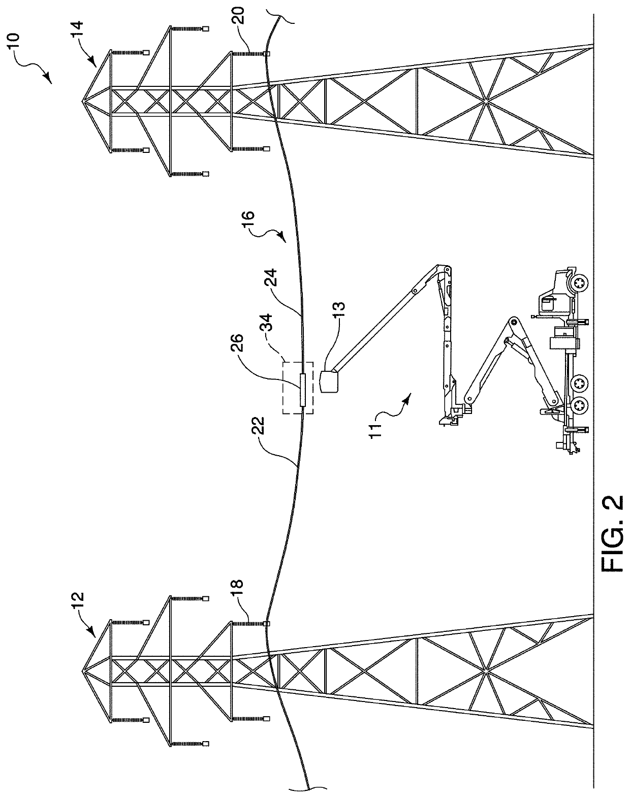
Pending Publication Date: 2021-11-25
QUANTA ASSOC
View PDF9 Cites 0 Cited by
  • Summary
  • Abstract
  • Description
  • Claims
  • Application Information

AI Technical Summary

Benefits of technology

The patent is about a device that helps protect electrical conductors from damage caused by blast and shock waves during the process of joining or terminating them. The device uses a special shield made of lightweight fabric that helps to reduce the impact and noise caused by the detonation of the device. This helps to prevent damage to nearby electronics. The device can be easily attached to the conductors using support arms.

Problems solved by technology

While implosion devices have typically been adequate in achieving the desired mechanical connection properties to safely join the two free ends of two conductors, while achieving the desired electrical connection of the two free ends, such implosion devices are not without limitations, and room for improvement exists.

Method used


Image

  • Implosion shield apparatus and method
  • Implosion shield apparatus and method
  • Implosion shield apparatus and method

Examples


Embodiment Construction

[0032]Turning now to a detailed description of the present teachings with reference to the accompanying Figures, features and concepts also may be manifested in other arrangements and so the scope of the teachings is not limited to the embodiments described or depicted in the Figures. The following examples of certain embodiments of the teachings are provided. Each example is provided by way of explanation of the teachings, one of many examples of the teachings, and the following examples should not be read to limit, or define, the scope of the teachings.

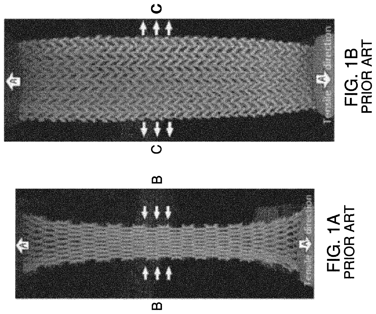
[0033]FIG. 1A illustrates, as is known in the prior art, the laterally constricting effect of a longitudinal tensile force acting on a length of conventional (positive Poisson's ratio) knitted fabric. FIG. 1B illustrates, as is also known in the prior art, the laterally expanding effect of a longitudinal tensile force acting on a length of auxetic (negative Poisson's ratio) knitted fabric. The usefulness of the laterally expanding e...


PUM


Abstract

An implosion shield of ballistic fabric adapted to mount so as to surround an implosion sleeve or dead-end on a power line. The implosion shield may be wrapped or formed as an envelope or tent including one piece and folded around the implosion sleeve or dead-end and secured with fasteners. A method of installing the implosion cover may include installing an implosion sleeve or dead-end on a power line, and then installing the implosion shield around the implosion sleeve or dead-end, by wrapping the implosion shield around the implosion sleeve or dead-end, or by securing an envelope implosion shield over the implosion sleeve or dead-end, or by draping the shield over the implosion sleeve or dead-end, or by mounting the shield on a frame over the implosion sleeve or dead-end, then detonating the implosion sleeve or dead-end. The implosion shield attenuates shock, pressure and sound waves from the detonation.

Description

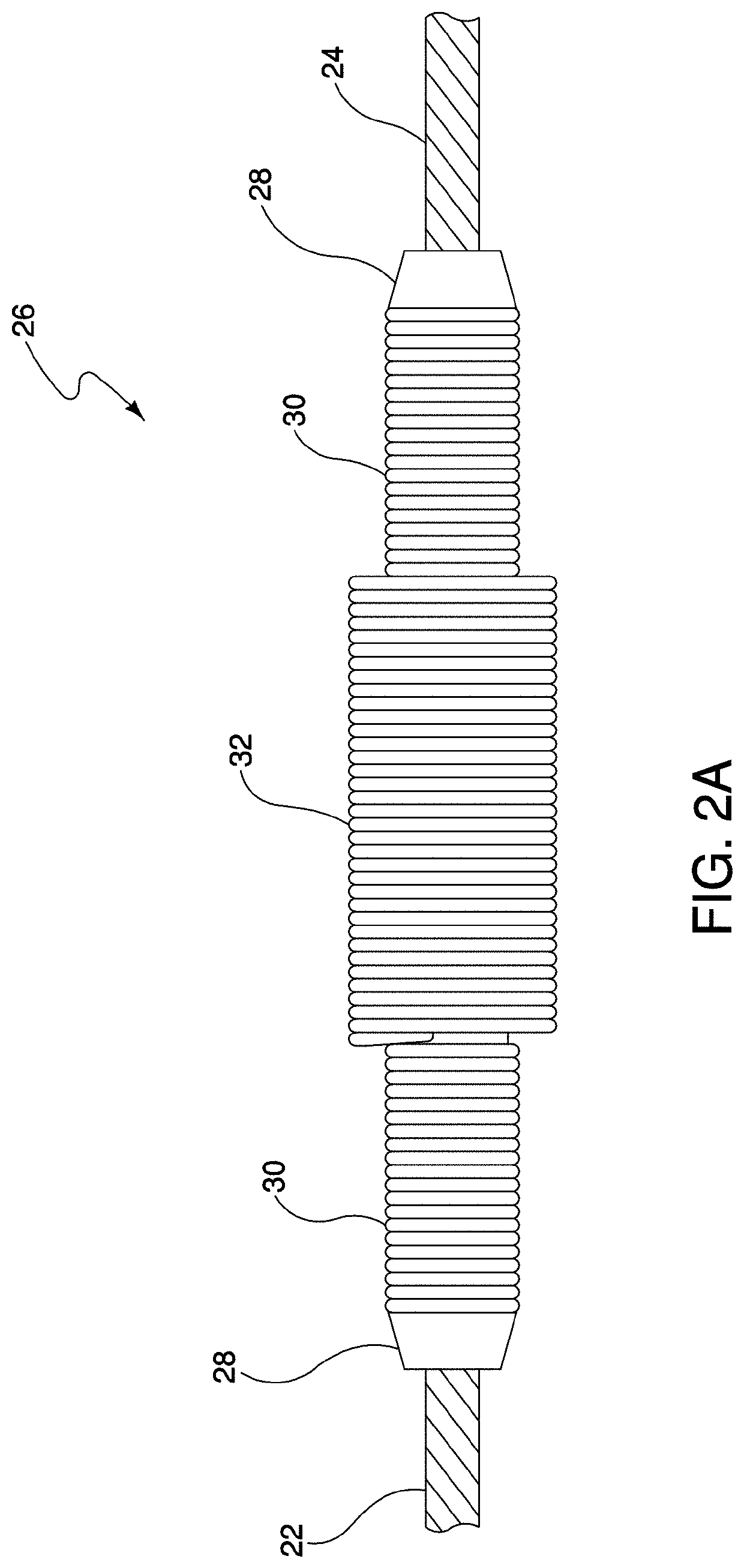
FIELD OF THE INVENTION[0001]This invention relates to an apparatus for shielding an implosion device used on a power line, a method of installing an apparatus for shielding an implosion device on a power line, and a method and apparatus for protecting adjacent apparatus such as insulators, tools, hoists, grips and slings and for protecting fragile items such as windows at a distance.BACKGROUND OF THE INVENTION[0002]In the process of electrically joining two free ends of separate electrical power line conductors to create a single, continuous electrically conductive joint, and a mechanical connection is typically used to join the two free ends and maintain electrical and mechanical integrity and requisite ampacity in the conductor. To achieve the requisite mechanical connection and to provide an electrically sufficient electrical connection, an implosion device may be used to form the joint and mechanical connection with the two free ends of the separate conductors. While implosion d...

Claims


Application Information

Patent Timeline
IPC IPC(8): F42D5/05D03D1/00D04B21/18H02G1/14H02G1/02
CPCF42D5/05D03D1/0052D04B21/18D10B2401/061H02G1/02D10B2505/00H02G1/14H01R4/08G10K11/162
Inventor WABNEGGER, DAVID KARLO'CONNELL, DANIEL NEILFERRARI, MARK DOUGLASHARVEY, BENJAMIN JAMES
Owner QUANTA ASSOC
Learn More