Table

a technology for tables and chairs, applied in the field of tables, can solve the problems of increasing costs, affecting the quality of tables, and the keyboard base of the workstation is not directly supported, and achieves the effect of simple structure and easy adjustment of height and tilt of the top pla

Inactive Publication Date: 2021-12-02
SUDOH FUMIO
View PDF0 Cites 3 Cited by
  • Summary
  • Abstract
  • Description
  • Claims
  • Application Information

AI Technical Summary

Benefits of technology

[0041]This table has, as a basic structure, a top plate, a plurality of leg units each having support column and foot, and a plurality of operating portions, each leg unit belonging to either a first leg unit group provided on one side of the top plate or a second leg unit group provided on the other side of the top plate; the support columns of the leg units belonging to the first leg unit group are variable in length by operating the operating portion, and the supports of the leg units belonging to the second leg unit group. The length of the support column of the leg unit belonging to the first leg unit group and the length of the support column of the leg unit belonging to the second leg unit group are changed by the operation of the first operation section or the second operating individually. When the lengths of the support columns are changed to the same length, the height of the table is changed. When the lengths of the support columns are changed to the different lengths, the table is tilted from one side to the other side, or the height and tilting of the table are changed. Since the operation unit is divided into two operation units of the first operation section and the second operation section, the user can make height adjustment and tilt adjustment by operating each operation section alone. Alternatively, two people can operate the respective operation sections. Each of the first operation section and the second operation section is itself a mechanism for changing the length of the leg unit which has been used in a lifting table capable of changing the height of the top plate. The table of this invention is provided, by utilizing and devising this mechanism, in which the structure thereof can be made as simple as possible, and the height and tilting of the top plate can be easily adjusted by operating the first operation section and the second operation section individually.

Problems solved by technology

In the height adjustment mechanism of the top plate disclosed in Patent Document 2, it requires a linkage mechanism with a complex structure for the adjustment operation, which takes time to manufacture, assemble and adjust, and also is the reason for the increased cost.
The keyboard base of this workstation is not support directly to support arms.
In general, it is conceivable that two air springs are operated simultaneously by operating a single operating lever, but with respect to such structure, it is inevitable that various errors occur inevitably in manufacturing and assembling the components that form the path from the operating lever to the push valve.
It is very difficult, for each table specification, to balance between such manufacturing and assembling errors and the rigidity of the operating rod which leads to deformation and distortion during the operation of the operating rod.
That is, if the rigidity of the operating rod is too high, the error appears directly as a difference in timing of pushing the valve, and if the rigidity of the operating rod is too low, the amount of operation of the operating rod is absorbed by the deformation and distortion, and the time of pushing the push valve changes, which does not ensure a sufficient amount of pushing pressure for the valve.
The result is that two or more air springs sometimes make it difficult to move up and down equal amounts, that is, it is difficult to carry out synchronized action.
In order to tilt the top plate relative to the support columns performed as parallel rinks, a mechanism for tilting the top plate and maintaining its tilted state is required between the top plate and the top plate support portion set on the upper part of the support columns, and the structure of the upper part of the support column and the top plate support portion has to be more complicated.

Method used


Image

  • Table
  • Table
  • Table

Examples


Embodiment Construction

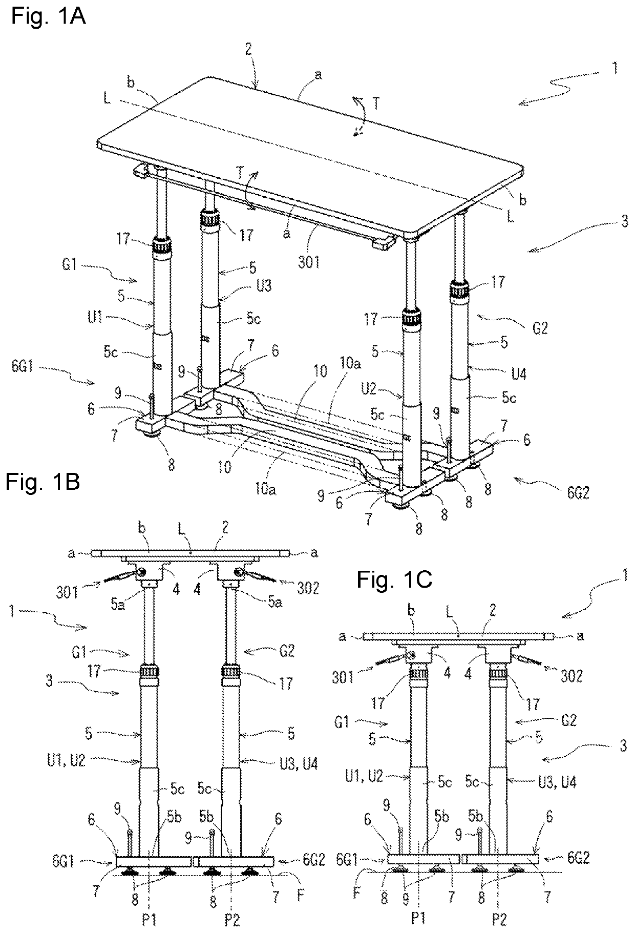
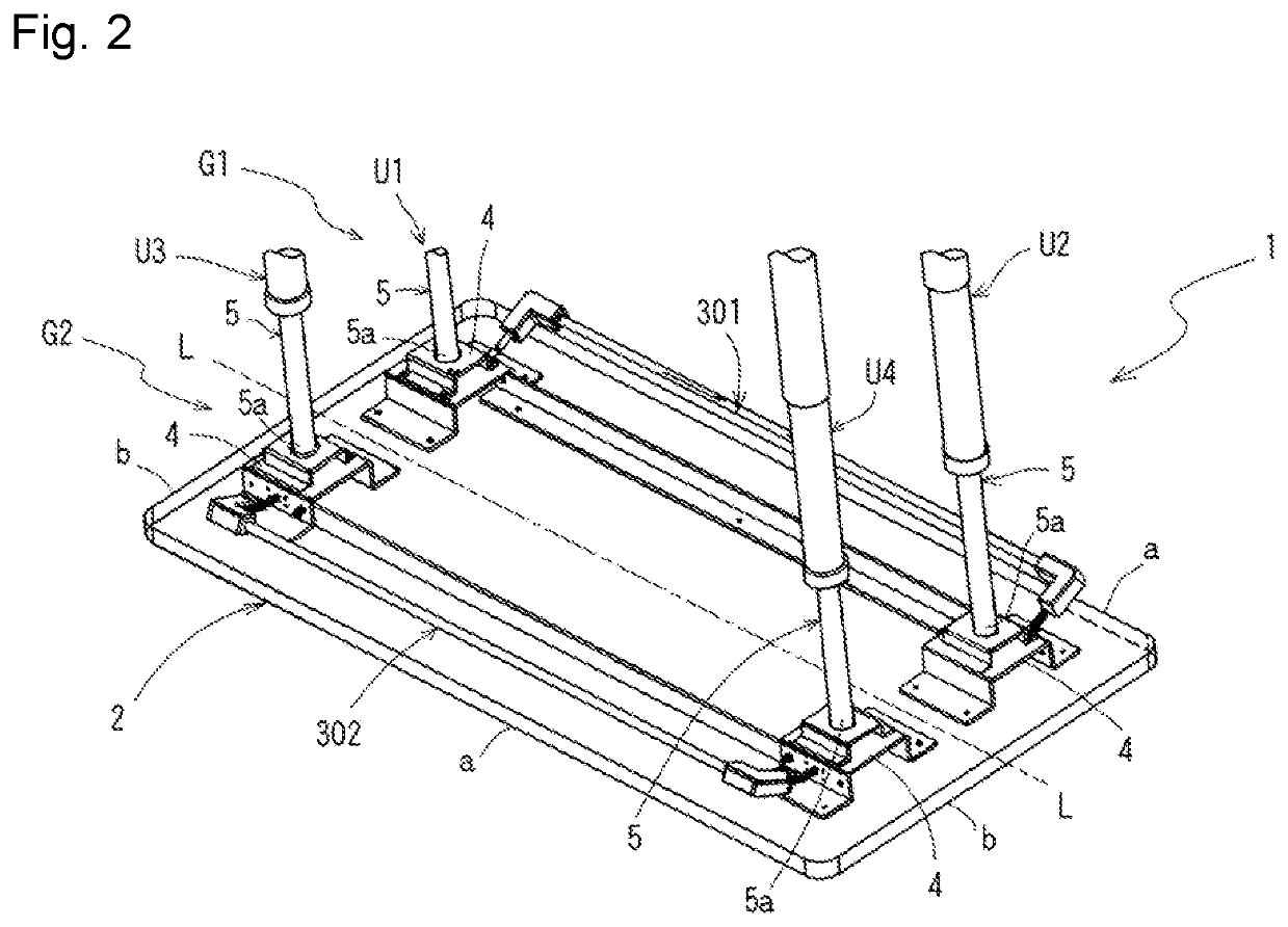
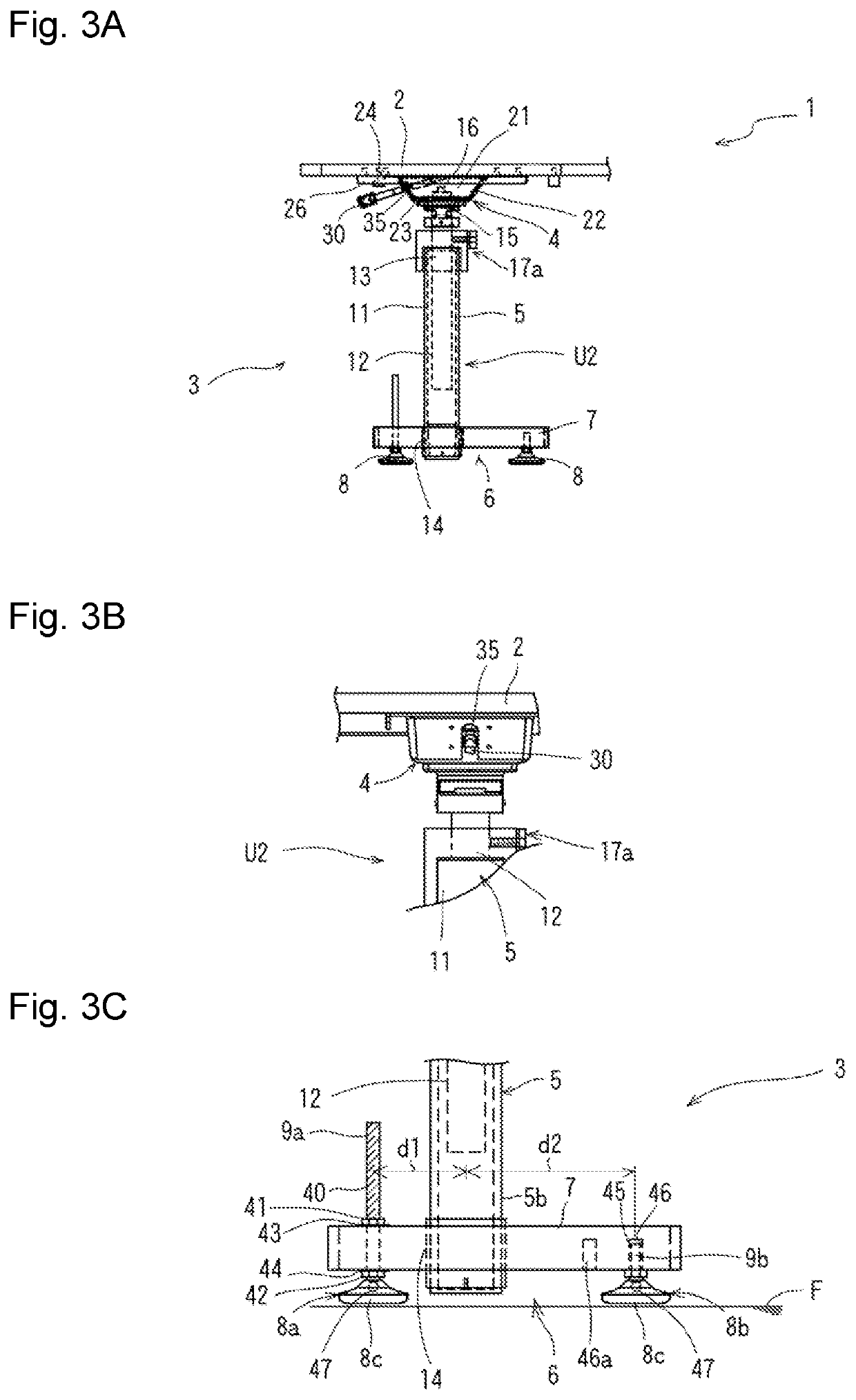
[0056]Referring now to the embodiments of the invention shown in the attached drawings, FIGS. 1A-5B are drawings representing an embodiment of the table. FIGS. 1A-1C show a perspective view and a side view of the first embodiment of the table according to the present invention. FIG. 2 shows a perspective view representing a portion of the table when viewed from the inside. FIGS. 3A-3C show the leg unit of this table, i.e., a leg structure including a support column and a foot section, and a top plate receiving structure for connecting the top plate and the support column. FIGS. 5A-5B are explanatory views showing the inclination of the top plate of the table.

[0057]FIGS. 1A-1C represent an implementation example of the table according to the present invention. FIG. 1A is a perspective view showing the table in which the top plate is in a high position and in a horizontal state, FIG. 1B is a side view thereof, and FIG. 1C is a side view showing the table in which the top plate is in a...


PUM


Abstract

Each of a plurality of leg units (U1 to U4) for supporting a top plate (2) have a support column (5) and a foot section (6). The plurality of leg units (U1 to U4) are divided into a first leg unit group (G1) along one long side edge “a” of the top plate (2) and a second leg unit group (G2) along the other long side edge “a”. The first operation units (301) corresponding to the first leg unit group (G1) and the second operation units (302) corresponding to the second leg unit group (G2) are operated individually, to change the lengths of the support columns (5) belonging to the leg unit set (G1) and the second leg unit set (G2) to the different lengths, so that the top plate (2) is tilted.

Description

CROSS REFERENCE TO RELATED APPLICATIONS[0001]This application claims priority from Japan Patent Application No. 2020-92787, filed May 27, 2020, the entire contents of which are herein incorporated by reference.FIELD OF TECHNOLOGY[0002]This invention concerns a table, which includes a top plate, several support columns which support the top plate and can change its height by operation, and foot sections, each of which is attached to the lower end of the support columns, and can support said support columns at ground level.BACKGROUND TECHNOLOGY[0003]Conventionally, the structure of such devices as office tables, furniture, setting tables, and working platforms (hereinafter defined as “tables” in this specification as a general term) included a top plate for setting items on its top surface or performing various operations, and one or more support columns to support the top plate. A solution with a height adjustment device for changing the height of the top plate is proposed.[0004]A ch...

Claims


Application Information

Patent Timeline
Patent Type & Authority Applications(United States)
IPC IPC(8): A47B9/20A47B9/16
CPCA47B9/20A47B9/16A47B9/10A47B13/021A47C3/30A47C7/002A47B2200/0042A47B2200/0051
Inventor SUDOH, FUMIO
Owner SUDOH FUMIO
Why Eureka
Try Eureka