
Reamer Wear Protection Assembly and Method

Pending Publication Date: 2021-12-02
INROCK DRILLING SYST INC
View PDF10 Cites 0 Cited by
  • Summary
  • Abstract
  • Description
  • Claims
  • Application Information

AI Technical Summary

Benefits of technology

This patent describes an apparatus that includes a reaming tool with inserts made of a material that can resist abrasion. These inserts are placed on the outer surface of the reaming tool in a way that they run parallel to the main axis of rotation. The technical effect of this design is that it improves the efficiency of the reaming tool by making it more resistant to wear and tear, which can help to prolong its lifespan and save time and money during the process. Additionally, the method of utilizing this apparatus is also provided, which involves using the inserted design in a specific way to achieve the best results.

Problems solved by technology

In operation, rotational friction between the outer surface of the corebuster and the rock being drilled results in abrasion of the outer surface of the corebuster.
Accordingly, corebusters possess a limited operational lifetime.

Method used


Image

  • Reamer Wear Protection Assembly and Method
  • Reamer Wear Protection Assembly and Method
  • Reamer Wear Protection Assembly and Method

Examples


Embodiment Construction

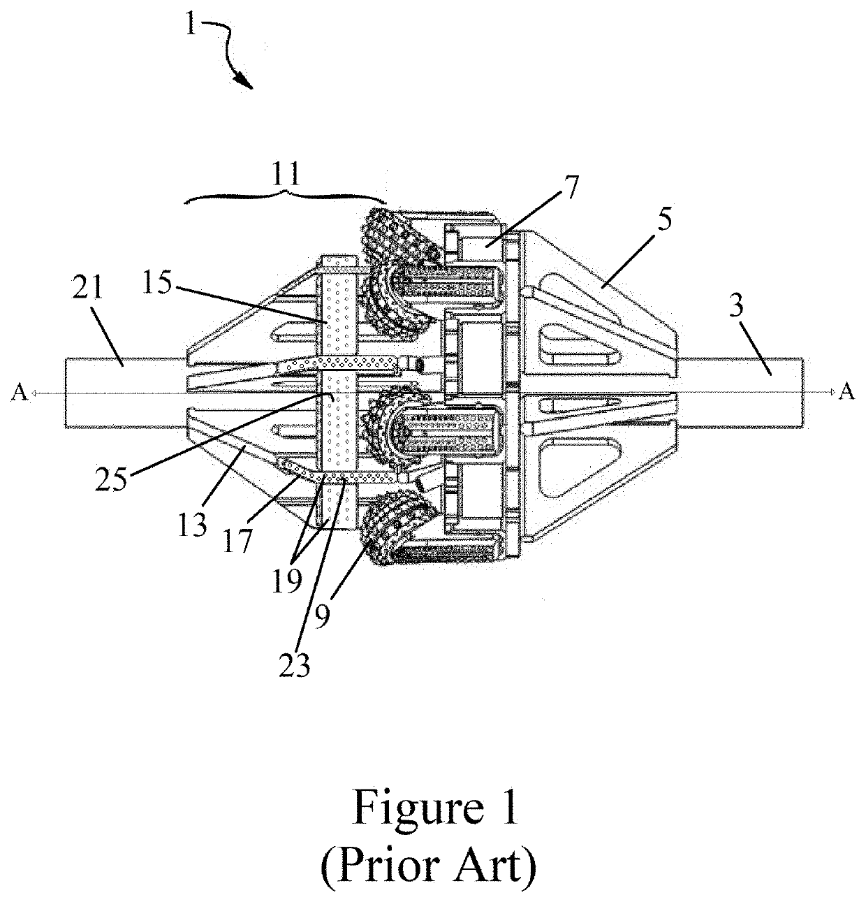
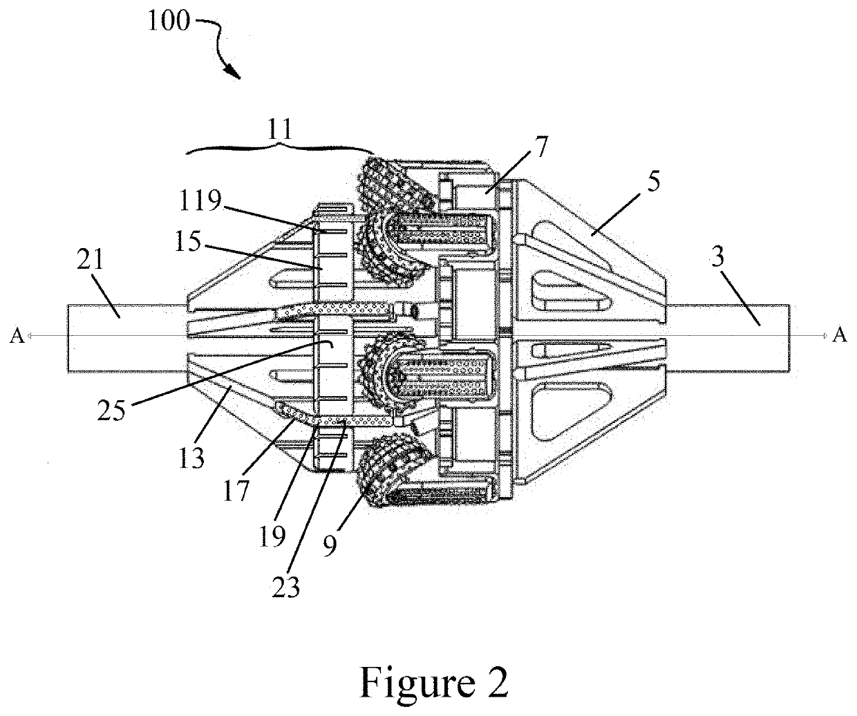
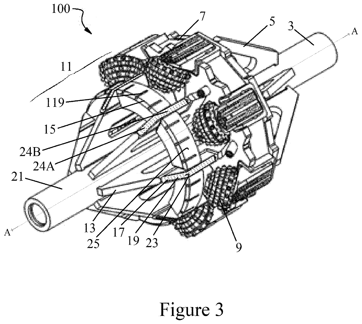
[0017]The exemplary embodiments are best understood by referring to the drawings with like numerals being used for like and corresponding parts of the various drawings. As used herein, longitudinal refers to the axis A-A identified in FIGS. 1 and 2 (i.e., the axis of rotation of the reamer), and axial refers to a direction perpendicular to axis A-A of FIGS. 1 and 2. The directions top and bottom as used in this specification are used for descriptive purposes only, and other orientations are contemplated.

[0018]Referring to FIG. 1, a prior art reamer 1 is depicted. As shown in FIG. 1, reamer 1 comprises an up-hole pipe section 3, up-hole gussets 5, fluid chambers 7, cutting elements 9, front end 11, and a down-hole pipe section (collar) 21. In the reamer depicted in FIG. 1, front end 11 comprises front-end gussets 13, longitudinal corebuster components 17, and axial corebuster components (“pie wedges”) 15. Longitudinal corebuster components 17 and / or pie wedges 15 may comprise a plura...


PUM


Abstract

Embodiments of a reamer of the present invention generally include a front end containing components, such as pie wedge-shaped corebuster components, that are substantially axially disposed with respect to the axis of rotation of the reamer, wherein the pie wedges include abrasion-resistant inserts, which may be cylindrical in shape, oriented substantially longitudinally with respect to the axis of rotation of the reamer. Embodiments of a method of using an apparatus of the present invention are also provided.

Description

CROSS-REFERENCE TO RELATED APPLICATIONS[0001]This application claims the benefit of U.S. Provisional Application No. 63 / 033,481, filed on Jun. 2, 2020, which application is incorporated herein by reference as if reproduced in full below.STATEMENT REGARDING FEDERALLY SPONSORED RESEARCH OR DEVELOPMENT[0002]Not applicable.BACKGROUND OF THE INVENTION[0003]This invention relates to an apparatus and method for sub-surface Horizontal Directional Drilling (HDD). HDD is utilized to create an underground pathway without excavation. An example of HDD may be found in U.S. Pat. No. 5,242,026 to Deken, et al., which is incorporated herein by reference in its entirety. One type of apparatus utilized in HDD is a borehole cutter, also known as a “reamer.” Examples of reamers may be found in U.S. Pat. No. 6,386,302 to Beaton, and U.S. Pat. No. 10,428,586 to Wagner et al., which are incorporated herein by reference in their entirety.DESCRIPTION OF THE RELATED ART[0004]Within the HDD industry, the unde...

Claims


Application Information

Patent Timeline
IPC IPC(8): E21B10/26E21B7/28E21B7/04
CPCE21B10/26E21B10/28E21B7/046E21B7/28
Inventor WAGNER, DAVID B.SHIPLEY, JERALD C.
Owner INROCK DRILLING SYST INC
Learn More