LED lamp arrangement with controlled power

Pending Publication Date: 2021-12-09
SILICON HILL
View PDF0 Cites 1 Cited by
  • Summary
  • Abstract
  • Description
  • Claims
  • Application Information

AI Technical Summary

Benefits of technology

[0011]It is therefore an object of the invention to provide an LED lamp which has a more stable la

Problems solved by technology

An undesirable result is a relatively low power factor and relatively high reactive power.
In some cases, a straightforward replacement of a florescent lamp by an LED lamp in a fluorescent luminaire results in a failure of the entire luminaire.
This can happen for example when the ballast is too old and/or is damaged after years of operat

Method used


Image

  • LED lamp arrangement with controlled power
  • LED lamp arrangement with controlled power
  • LED lamp arrangement with controlled power

Examples


Example

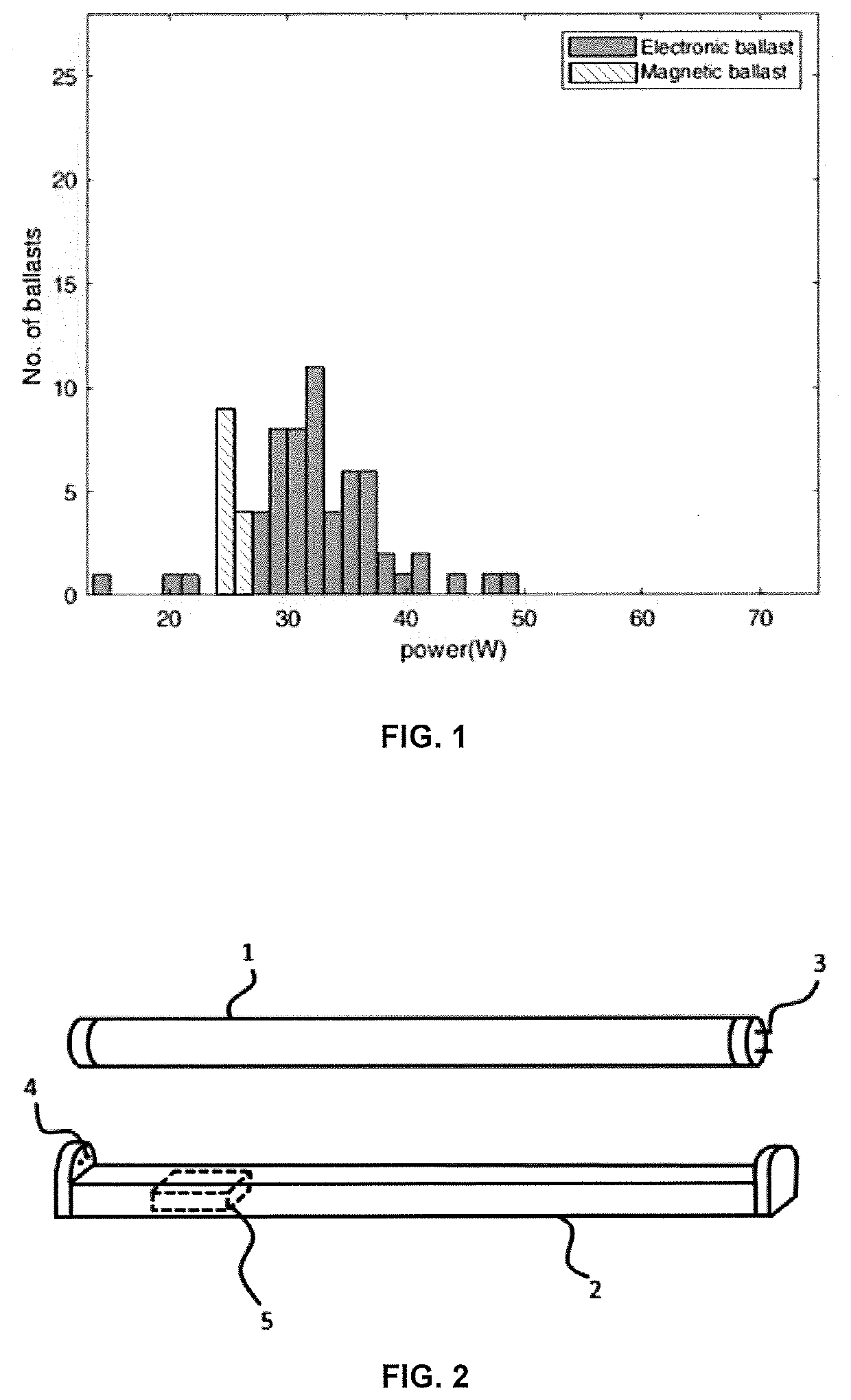
[0026]The following is a more detailed explanation of exemplary embodiments of the invention. FIG. 2 shows an LED lamp 1 adapted for installation in a luminaire 2 designed for a fluorescent tube, the LED lamp 1 preferably having a size and shape to enable installation into the luminaire 2 without modification. Two electrical connectors 3 (usually in the form of pins) are provided at each end of the LED lamp 1, for releasably connecting to corresponding connectors 4 of the luminaire. The luminaire 2 may include a ballast 5 or may have no ballast. The ballast 5, if included in the luminaire, may be a magnetic ballast, an electronic ballast which operates as a constant current ballast, or an electronic ballast which operates as a constant power ballast.

[0027]The luminaire 2 provides electrical power to the LED lamp 1 via the connectors 4. The electrical power provided by the luminaire 2 which is input to the LED lamp 1 will vary depending on the design of the luminaire, i.e. whether th...


PUM


Abstract

An LED lamp (1) for use in a luminaire (2), the LED lamp (1) comprising a plurality of LEDs (14) connected in a plurality of groups (15, 16); one or more rectifier circuits (10, 10a, 10b) adapted for rectifying an electrical current received from the luminaire (2) for supply to the LEDs (14); a first control circuit (24) adapted to estimate electrical current or electrical power received by or used by the LED lamp (1), and adapted to generate an output on the basis of the estimate; and a switching circuit (20) comprising a first switch (21) for switching the plurality of groups of LEDs (15, 16) between a plurality of different circuit configurations at a switching frequency of at least 300 kHz and according to a duty cycle; wherein the switching circuit (20) is configured to adjust the duty cycle in dependence on the output of the first control circuit (24) to adjust the electrical power used by the LED lamp (1).

Description

TECHNICAL FIELD[0001]The invention relates generally to light emitting diode (LED) lamps and LED lighting, and more particularly to LED lamps suitable to replace a fluorescent lamp in a luminaire having a ballast for use with fluorescent lamps.BACKGROUND[0002]Fluorescent lighting has been around for many years. This form of lighting started out as a highly efficient alternative for incandescent light bulbs, but has recently been surpassed by LED lighting in terms of efficiency and power consumption, and also in other aspects as set out below.[0003]Fluorescent lamps generally comprise a tube filled with an inert gas and a small amount of mercury, capped at both ends with double pinned end caps. The end caps contain a glow wire to preheat the gasses inside the tube and to vaporize the mercury in order to assist with ignition of the fluorescent lamp. After the user turns on a main switch (e.g. a wall switch or a cord switch on the ceiling), the fluorescent lamp is ignited, and heat gen...

Claims


Application Information

Patent Timeline
IPC IPC(8): H05B45/3574H05B45/3725H05B45/305H05B44/00
CPCH05B45/3574H05B45/305H05B45/3725H05B45/48H05B45/3578Y02B20/30
Inventor ROY, SHOUNAKFERRÉ VILA, RAMONRICHARDSON, ROSEMARY
Owner SILICON HILL
Why Eureka
Try Eureka