Imaging lens
- Summary
- Abstract
- Description
- Claims
- Application Information
AI Technical Summary
Benefits of technology
Problems solved by technology
Method used
Image

Examples
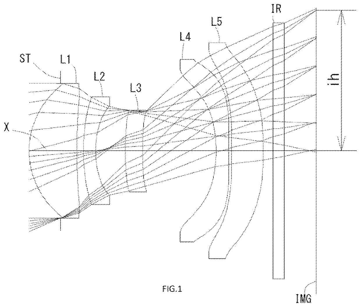
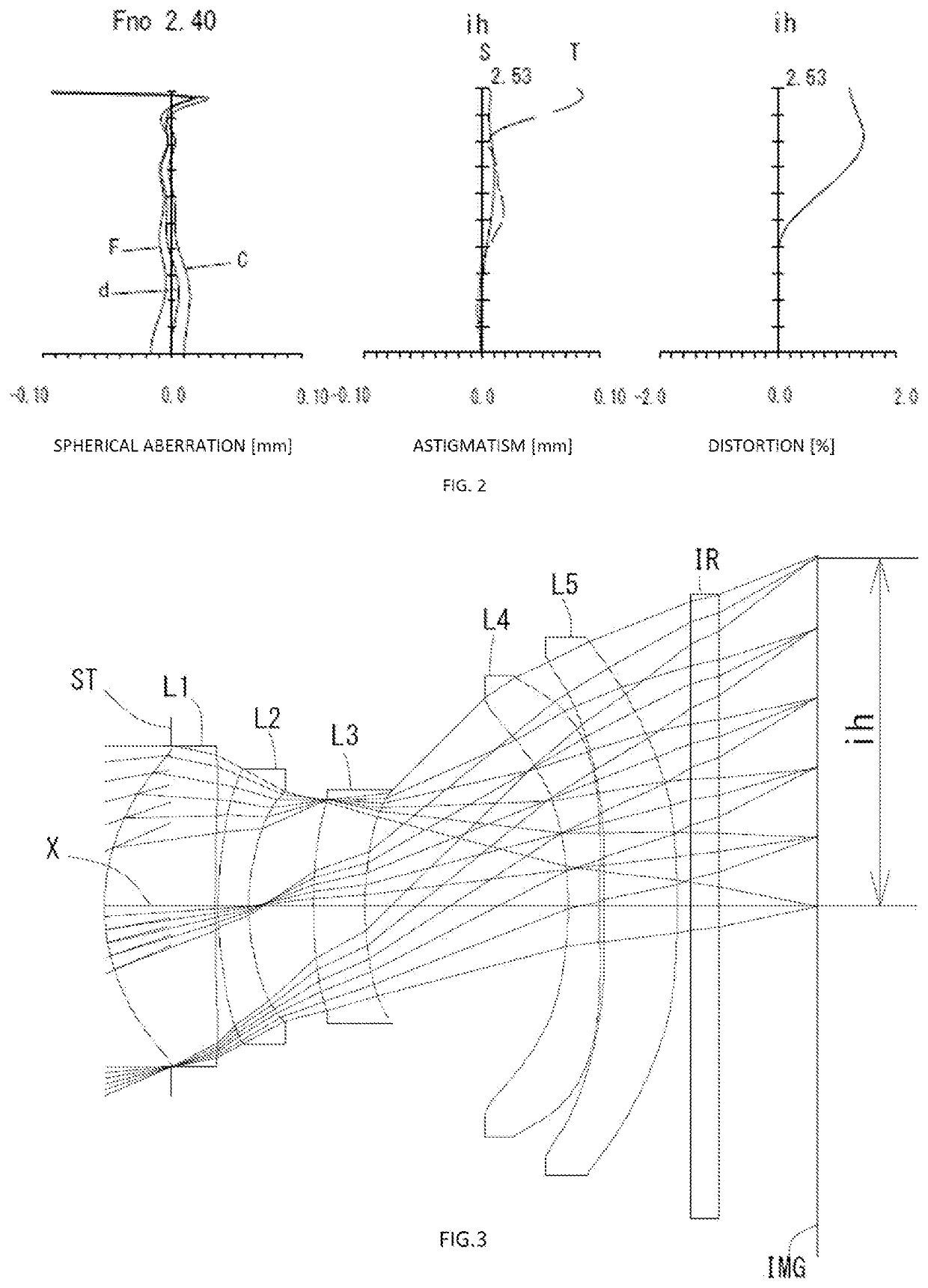
example 1
[0157]The basic lens data is shown below in Table 1.
TABLE 1Example 1Unit mmf = 5.86Fno = 2.40ω(°) = 23.1h = 2.53TTL = 5.13Surface DatairdNdνd(Object)InfinityInfinity1 (Stop)Infinity−0.56342*1.47570.86711.54456.44(νd1)3*11.82180.11554*2.76880.22041.67119.24(νd2)5*1.50310.54126*6.31890.30861.67119.24(νd3)7*6.23631.33428*−2.66380.23001.54456.44(νd4)9*8.74850.053710* 19.36580.57241.67119.24(νd5)11* −8.28880.171112 Infinity0.21001.51764.2013 Infinity0.5819Image PlanInfinityConstituent Lens DataLensStart SurfaceFocal Length123.00824−5.271361423.83048−3.7245108.726Aspheric Surface DataSecond SurfaceThird SurfaceFourth SurfaceFifth SurfaceSixth SurfaceSeventh Surfacek 5.373314E−02 9.900000E+01 0.000000E+00 0.000000E+00 0.000000E+000.000000E+00A4−4.203258E−03−9.843941E−02−3.095735E−01−2.714841E−01−1.269534E−023.564621E−02A6−2.323671E−02 7.333767E−01 1.631297E+00 1.364467E+00 5.653049E−011.579969E−01A8 2.112389E−01−3.130599E+00−7.656376E+00−6.551568E+00−6.100420E+009.243651E−03A10−7.297688E−0...
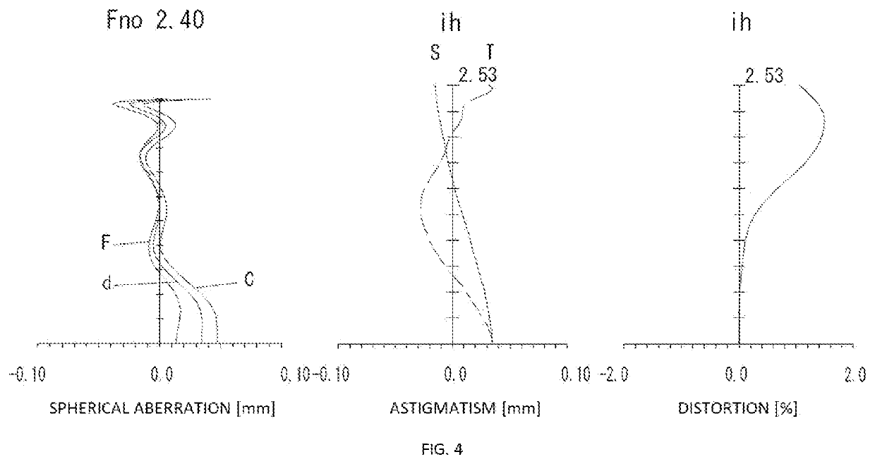
example 2
[0160]The basic lens data is shown below in Table 2.
TABLE 2Example 2Unit mmf = 5.86Fno = 2.40ω(°) = 23.4h = 2.53TTL = 5.14Surface DatairdNdνd(Object)InfinityInfinity1 (Stop)Infinity−0.49022*1.51390.81181.54456.44(νd1)3*10.61420.02444*2.37620.22331.67119.24(νd2)5*1.46380.47586*3.56680.38261.53555.69(νd3)7*3.05151.49258*−3.11380.23011.54456.44(νd4)9*8.90560.035010* 16.03870.53391.67119.24(νd5)11* −10.48450.100012 Infinity0.21001.51764.2013 Infinity0.6877Image PlanInfinityConstituent DataLensStart SurfaceFocal Length123.14424−6.30336−53.27448−4.2095109.529Aspheric Surface DataSecond SurfaceThird SurfaceFourth SurfaceFifth SurfaceSixth SurfaceSeventh Surfacek−2.847673E−01 7.556141E+01 0.000000E+000.000000E+000.000000E+000.000000E+00A41.241276E−02−2.100620E−01−3.967441E−01−2.699478E−01 3.292716E−024.146010E−02A62.043712E−02 1.065880E+00 1.306870E+003.510321E−01−2.329795E−01 4.574907E−01A8−6.359233E−02 −3.126032E+00−3.231874E+001.818645E+009.094634E−01−2.268993E+00 A101.007985E−01 5.5091...
example 3
[0163]The basic lens data is shown below in Table 3.
TABLE 3Example 3Unit mmf = 5.85Fno = 2.40ω(°) = 23.4h = 2.53TTL = 5.18Surface DatairdNdνd(Object)InfinityInfinity1 (Stop)Infinity−0.49462*1.49800.79151.54456.44(νd1)3*9.98920.11814*2.73710.22241.67119.24(νd2)5*1.44640.53056*3.21140.29771.53555.69(νd3)7*4.29491.52718*−2.62710.23231.54456.44(νd4)9*8.22340.087410* 14.92720.63141.67119.24(νd5)11* −8.54700.242612 Infinity0.21001.51764.2013 Infinity0.3609Image PlanInfinityConstituent DataLensStart SurfaceFocal Length123.13424−4.9133621.72348−3.6305108.191Aspherical Surface DataSecond SurfaceThird SurfaceFourth SurfeceFifth SurfaceSixth SurfaceSeventh Surfacek−3.914038E−016.480447E+01 1.563022E+00 2.605099E−012.015131E+00 5.384873E−01A4−2.743047E−022.229868E−02−1.322745E−01−3.121998E−011.644145E−02−7.026743E−02A6 3.005483E−01−4.852711E−01 −3.309096E−01 2.269034E+00−4.723194E−01 1.629350E+00A8−1.181057E+002.444892E+00 2.807361E+00−1.863274E+014.467572E+00−1.109831E+01A10 2.690534E+00−6.35...
PUM
 Abstract
Description
Claims
Application Information
 - Generate Ideas
- Intellectual Property
- Life Sciences
- Materials
- Tech Scout
- Unparalleled Data Quality
- Higher Quality Content
- 60% Fewer Hallucinations
Browse by: Latest US Patents, China's latest patents, Technical Efficacy Thesaurus, Application Domain, Technology Topic, Popular Technical Reports.
© 2025 PatSnap. All rights reserved.Legal|Privacy policy|Modern Slavery Act Transparency Statement|Sitemap|About US| Contact US: help@patsnap.com