Retainer gripping device

a technology of a gripping device and a clamping rod, which is applied in the direction of manufacturing tools, machines/engines, mechanical equipment, etc., can solve the problems of assembly defect elimination and assembly defect elimination, and achieve the effect of not eliminating assembly d

Pending Publication Date: 2021-12-30
TOYOTA JIDOSHA KK +1
View PDF0 Cites 0 Cited by
  • Summary
  • Abstract
  • Description
  • Claims
  • Application Information

AI Technical Summary

Benefits of technology

[0004]Now, even when the cotters accommodated in the retainer meet product standards, there will be variations in the product dimensions thereof. The state of the cotters accommodated within the retainer may vary due to such variations in product dimensions. For example, when a lower end edge portion of a cotter protrudes too far from a lower end edge portion of the retainer accommodating

Problems solved by technology

For example, when a lower end edge portion of a cotter protrudes too far from a lower end edge portion of the retainer accommodating the cotter, the valve stem may thrust the cotter upward at the time of pressing the retainer from above the valve to mount to th

Method used


Image

  • Retainer gripping device
  • Retainer gripping device
  • Retainer gripping device

Examples


embodiment

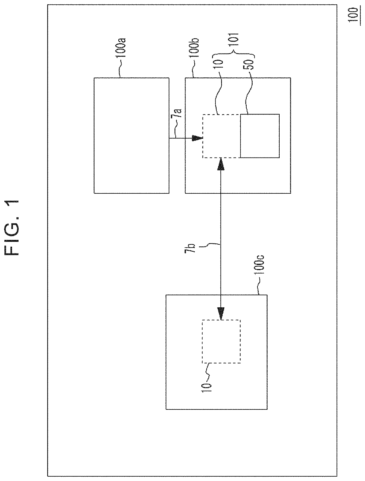
[0028]A schematic configuration of a valve assembling device 100 including a retainer gripping device 101 according to the embodiment will be described first with reference to FIGS. 1, 2, 3A and 3B. The valve assembling device 100 includes a retainer supply unit 100a, a retainer gripping stand 100b, and a valve assembling stand 100c, as illustrated in FIG. 1. A seat portion 50 included in the retainer gripping device 101 is provided to the retainer gripping stand 100b. A retainer gripping unit 10 included in the retainer gripping device 101 is capable of moving between a position facing the seat portion 50, and the valve assembling stand 100c, as indicated by arrow 7b.

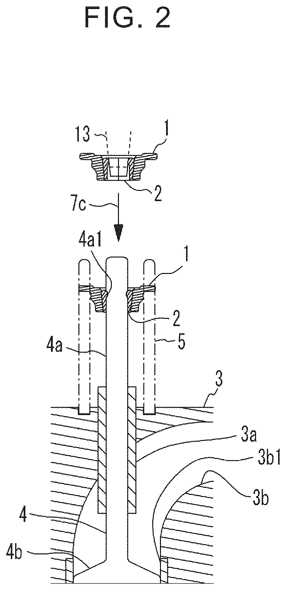
[0029]The valve assembling device 100 mounts a retainer 1 to a valve stem 4a of a valve 4 via cotters 2, as illustrated in FIG. 2. Mounting of such a retainer 1 is performed on the valve assembling stand 100c. A cylinder head 3 with the valve 4 and a valve spring 5 placed thereon is conveyed to the valve assembling st...


PUM


Abstract

A retainer gripping device, configured to grip a retainer accommodating a set of cotters inside the retainer, includes a retainer gripping unit, a retainer supporting portion, and a cotter supporting portion. The retainer gripping unit is configured to grip the retainer. The retainer supporting portion is configured such that the retainer gripped by the retainer gripping unit is placed in a state in which the set of cotters are accommodated inside the retainer. The cotter supporting portion is configured to support lower end edge portions of the cotters accommodated inside the retainer in a state in which the lower end edge portions are lifted upward higher than a lower end edge portion of the retainer.

Description

CROSS-REFERENCE TO RELATED APPLICATION[0001]This application claims priority to Japanese Patent Application No. 2020-111296 filed on Jun. 29, 2020, incorporated herein by reference in its entirety.BACKGROUND1. Technical Field[0002]The present disclosure relates to a retainer gripping device.2. Description of Related Art[0003]There is known a valve spring assembling device that assembles valves for intake and exhaust of an internal combustion engine to a cylinder head along with valve springs (see Japanese Unexamined Patent Application Publication No. 10-61420 (JP 10-61420 A), for example). By using such a valve spring assembling device, a valve spring is clamped between a retainer mounted to an end portion of a valve stem and the cylinder head. The retainer has a conical form, and is used in a state with a set of cotters accommodated therein. The retainer accommodating the cotters therein is gripped by a retainer gripping device, and is conveyed to an area above the cylinder head in...

Claims


Application Information

Patent Timeline
IPC IPC(8): B25J15/00
CPCB25J15/0038B23Q3/06B23P19/048B23P19/045F01L2303/01F01L1/462F01L3/10B25B27/24
Inventor OGAWA, RYOICHIKAWAI, YASUHIRO
Owner TOYOTA JIDOSHA KK
Why Eureka
Try Eureka