
Dampered drop plug

a technology of hydraulic actuation and drop plug, which is applied in the direction of fluid removal, borehole/well accessories, sealing/packing, etc., can solve the problems of failure of seat elements, failure of second shear elements, and failure of the seat elements

Active Publication Date: 2012-07-12
SCHLUMBERGER TECH CORP
View PDF2 Cites 31 Cited by
  • Summary
  • Abstract
  • Description
  • Claims
  • Application Information

AI Technical Summary

Benefits of technology

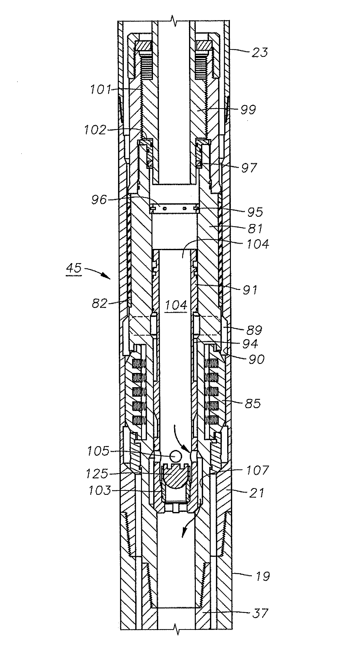
[0011]In accordance with an embodiment of the present invention, a dampered drop plug configured to be dropped down a bore of a drill string comprises a retainer configured to land on an upward facing shoulder of a tubular sleeve, and a plug releasably coupled to the retainer. The plug couples to the retainer while at a first pressure in the bore and decouples from the retainer at a second pressure in the bore. The retainer controls the flowrate of a fluid passing through the retainer after the plug decouples from the retainer.
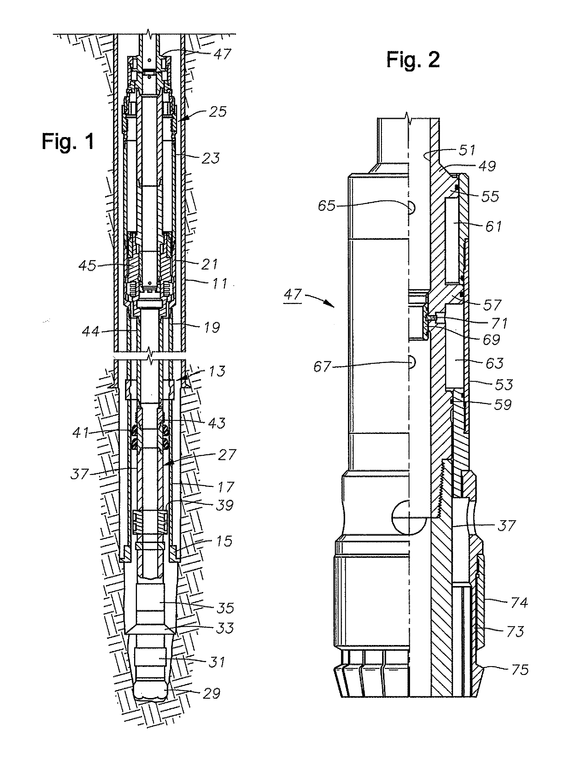
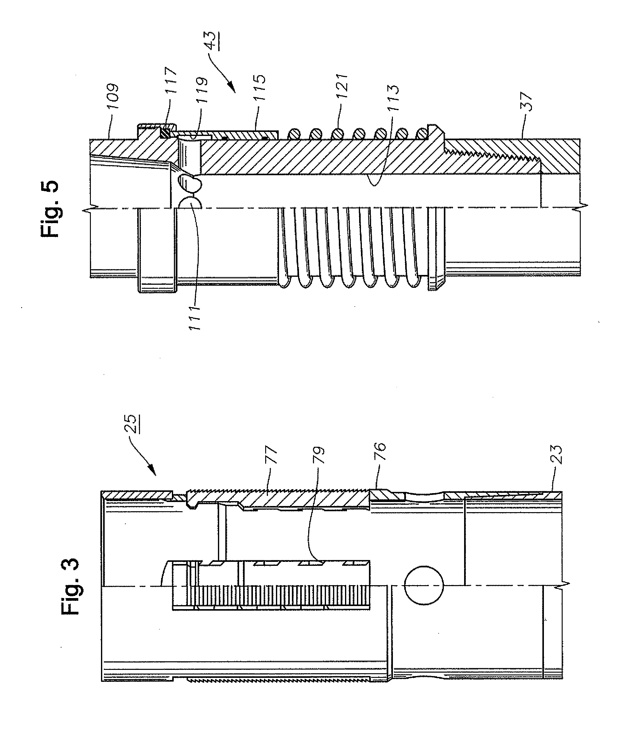
[0012]In accordance with another embodiment of the present invention, a downhole tool for actuating a first and second function while dampening a water hammer effect comprises a tubular mandrel having an inner passage and an upper end that secures to a string of conduit to receive a flow of fluid, and an outer sleeve sealingly surrounding and axially movable relative to the mandrel. The outer sleeve defines an annulus between the outer sleeve and the mandrel. A piston is interposed between the mandrel and the outer sleeve, defining upper and lower chambers in the annulus. The tool further comprises an upper fluid port between the inner passage of the mandrel and the upper chamber, and a lower fluid port between the inner passage of the mandrel and the lower chamber. The chambers have piston areas configured such that pressurized fluid flow from the inner passage simultaneously into both of the ports causes a net axial force on the outer sleeve to move the outer sleeve and an engaging member in a first axial direction to actuate the first function. Pressurized fluid flowing through only the upper fluid port causes a net axial force on the outer sleeve to move the outer sleeve and the engaging member in a second axial direction to actuate the second function. The tool also comprises a dampered drop plug, and a seat in the inner passage between the upper and lower fluid ports. The dampered drop plug is configured to control the pressurized fluid flow through the inner passage following actuation of the second function. The seat is positioned such that positioning the dampered drop plug on the seat prevents communication of the pressurized fluid flow with the lower chamber, and allows communication of the pressurized fluid flow with the upper chamber.
[0014]An advantage of a preferred embodiment is that the dampered drop plug disclosed herein provides a means to actuate a plurality of hydraulically actuated functions in a downhole tool while dampening any water hammer effect associated with prior art drop ball methods and apparatuses. This dampening advantageously prevents premature shear of shear seat elements downhole from the actuation of the first function. In addition, the dampered drop plug disclosed herein can employ reusable parts and materials, extending the life of the dampered drop plug.

Problems solved by technology

However, the liner does not extend back to the wellhead assembly at the surface.
At this point, the shear elements of the seat fail, and the ball and seat fall, allowing the pressurized fluid to flow down the well.
This then causes the second shear elements to fail prior to activation of the second hydraulically activated tool.

Method used


Image

  • Dampered drop plug
  • Dampered drop plug
  • Dampered drop plug

Examples


Embodiment Construction

[0029]The present invention will now be described more fully hereinafter with reference to the accompanying drawings which illustrate embodiments of the invention. This invention may, however, be embodied in many different forms and should not be construed as limited to the illustrated embodiments set forth herein. Rather, these embodiments are provided so that this disclosure will be thorough and complete, and will fully convey the scope of the invention to those skilled in the art. Like numbers refer to like elements throughout, and the prime notation, if used, indicates similar elements in alternative embodiments.

[0030]In the following discussion, numerous specific details are set forth to provide a thorough understanding of the present invention. However, it will be obvious to those skilled in the art that the present invention may be practiced without such specific details. Additionally, for the most part, details concerning drilling rig operation, materials, and the like have ...


PUM


Abstract

A dampered drop plug drops down a bore of a drill string. The dampered drop plug includes a retainer configured to land on an upward facing shoulder of a tubular sleeve, and a plug releasably coupled to the retainer. The plug couples to the retainer while at a first pressure in the bore and decouples from the retainer at a second pressure in the bore. The dampered drop plug lands on the upward facing shoulder of a tubular sleeve and actuates a first function. The plug then releases from the retainer, and passes fluid through the retainer at a controlled flowrate. The plug then lands on a ball seat and actuates a second function.

Description

BACKGROUND OF THE INVENTION[0001]1. Field of the Invention[0002]The present invention relates in general to a method and apparatus for hydraulic actuation of a downhole tool and, in particular, to an apparatus and method for actuating one or more functions of a downhole tool with a dampered drop plug.[0003]2. Brief Description of Related Art[0004]A variety of tools exist to perform downhole functions in a well. Some tools may be actuated in response to mechanical movement or manipulation of the drill pipe, including rotation. Others may be actuated by dropping a ball or dart into the drill string, then applying fluid pressure to the interior of the string after the ball or dart lands on a seat in the tool. The tool may be attached to the liner hanger or body of a running tool by threads, shear elements, or by a hydraulically actuated arrangement.[0005]Oil and gas wells are conventionally drilled with drill pipe to a certain depth, then casing is run and cemented in the well. The ope...

Claims


Application Information

Patent Timeline
Patent Type & Authority Applications(United States)
IPC IPC(8): E21B33/10
CPCE21B34/14E21B33/16E21B34/142E21B33/165E21B23/0413
Inventor NIKIFORUK, KEVIN JAMES
Owner SCHLUMBERGER TECH CORP
Learn More