Device for Supporting and Relieving the Arms of a User

Pending Publication Date: 2022-01-20
HILTI AG
View PDF0 Cites 0 Cited by
  • Summary
  • Abstract
  • Description
  • Claims
  • Application Information

AI Technical Summary

Benefits of technology

[0015]The shoulder movements of the user can consist for example in that the shoulders are raised while a user is working. For the purposes of the invention, this raising of the shoulder is preferably also referred to as shoulder elevation. Preferably, the supporting device is designed to synchronize an elevation of a user's shoulders with the device. In particular, the structure of the provided supporting device makes it possible for the rotary joint of the device, when the upper extremity is raised, to be adjusted upward by a height difference Ah. This has the advantageous result that a height offset is compensated. As a result of this compensation of the shoulder elevation, the supporting device can follow movements of the human body better, and so much more effective support of the user is allowed tha

Problems solved by technology

However, the operating principle of the conventional supporting devices, which is based on absorption or compensation of forces by a resilient element, is associated with the drawback that the supporting force provided by the elastic element also continues to act in an end position, such that the user's arms are pushed out of a desired position.
Moreover, when th

Method used


Image

  • Device for Supporting and Relieving the Arms of a User
  • Device for Supporting and Relieving the Arms of a User
  • Device for Supporting and Relieving the Arms of a User

Examples


Example

DETAILED DESCRIPTION OF THE DRAWINGS

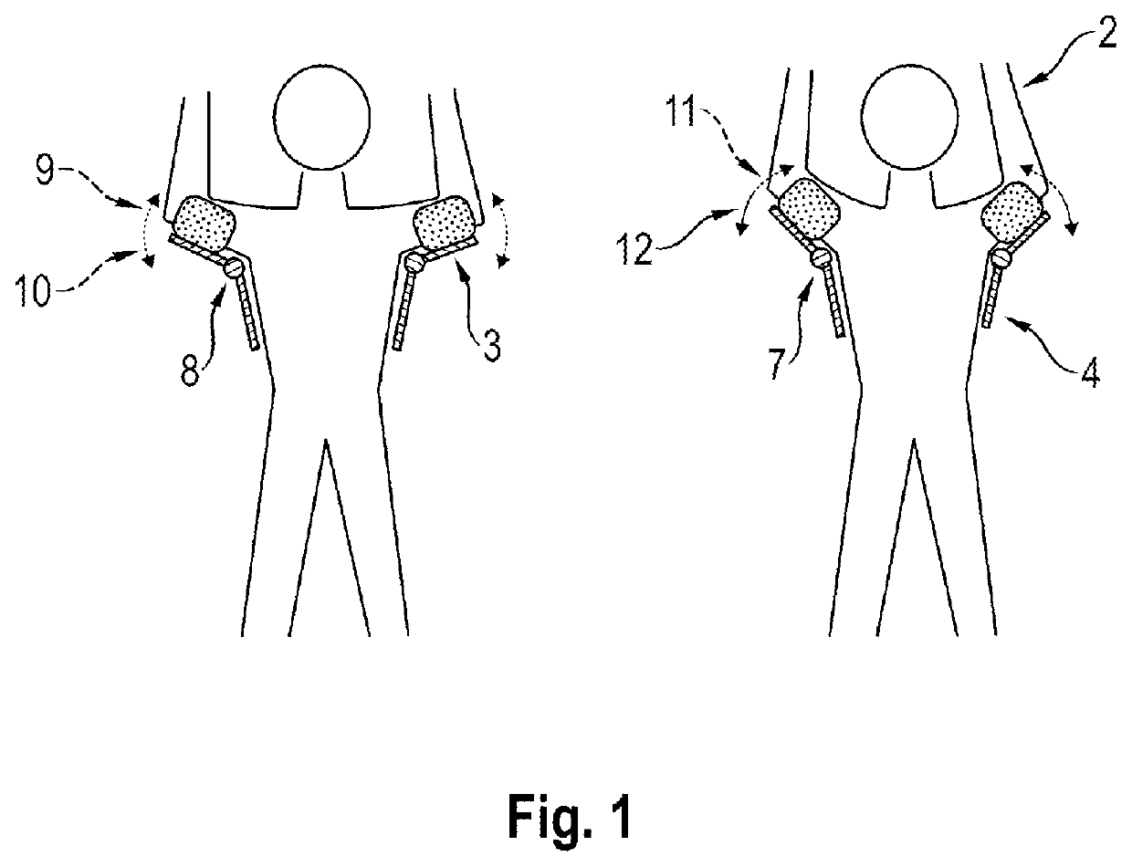
[0028]FIG. 1 shows, in the left-hand half of the image, the deactivated state and, in the right-hand half of the image, the activated state of a preferred configuration of the provided supporting device (1). Illustrated in each case is a user, who wishes to carry out for example overhead work with a power tool using their arms (2). Shown in the schematic illustration in FIG. 1 is in particular the upper subregion (3) and the lower subregion (4) of the supporting device (1). The upper subregion (3) is present preferably on an inner side of the user's upper arm (2), wherein the expression “inner side” preferably relates to the fact that, with the arms (2) not raised, one side of the arm faces the torso. This side of the arm (2) facing the torso is preferably referred to, for the purposes of the invention, as the inner side, while the side of the torso facing the upper arm is referred to as the side of the torso. Preferably, the lower subregion (4) o...


PUM


Abstract

A device for supporting and relieving a load on an arm of a user includes an upper subregion, a lower subregion, and a joint that has a horizontal axis of rotation where the upper subregion and the lower subregion are connected by the joint such that the upper subregion is pivotable in an upper spatial direction and a lower spatial direction about the horizontal axis of rotation of the joint. The joint is pivotable in the upper spatial direction and the lower spatial direction in a first state and is pivotable only in the upper spatial direction in a second state.

Description

BACKGROUND AND SUMMARY OF THE INVENTION[0001]The present invention relates to a device for supporting and relieving the load on a right arm and / or a left arm of a user, wherein the device comprises, for each side of the body, an upper subregion and a lower subregion, wherein the subregions can be connected by a joint such that the upper subregion is pivotable in an upper and a lower spatial direction about a horizontal axis of rotation of the joint. In particular, the supporting device is characterized in that it can be operated in preferably two different states.[0002]Conventional supporting devices, which are also known for example as passive exoskeletons for supporting the upper extremities of a user, are known from the prior art. The upper extremities of a user are in particular the arms of the user. These passive supporting devices, in order to be able to ensure the support, frequently use the restoring force of resilient elements in order to compensate for example for the weig...

Claims


Application Information

Patent Timeline
IPC IPC(8): A61H1/02
CPCA61H1/0281A61H1/0277A61H2201/1676A61H2201/1673A61H2201/0192A61H2201/1638A61F5/3753A61F5/013A61F2005/0165B25J9/0006
Inventor KAESMANN, SIMONMELZER, LARS
Owner HILTI AG
Why Eureka
Try Eureka