

Adjustable-incline climbing wall
a climbing wall and adjustable technology, applied in the direction of sports equipment, etc., can solve the problems that the climbing wall designed for climbing gyms is not well suited to home installation, and achieve the effect of reducing or eliminating the unusable “dead space”
- Summary
- Abstract
- Description
- Claims
- Application Information
AI Technical Summary
Benefits of technology
Problems solved by technology
Method used
Image

Examples
Embodiment Construction
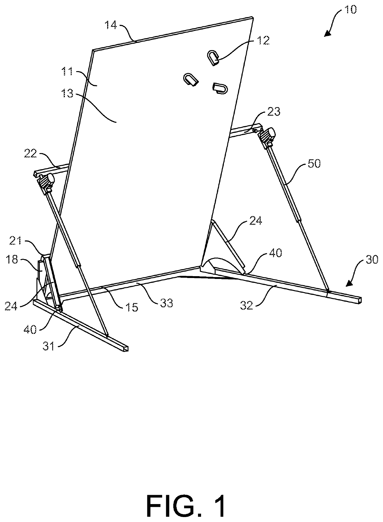
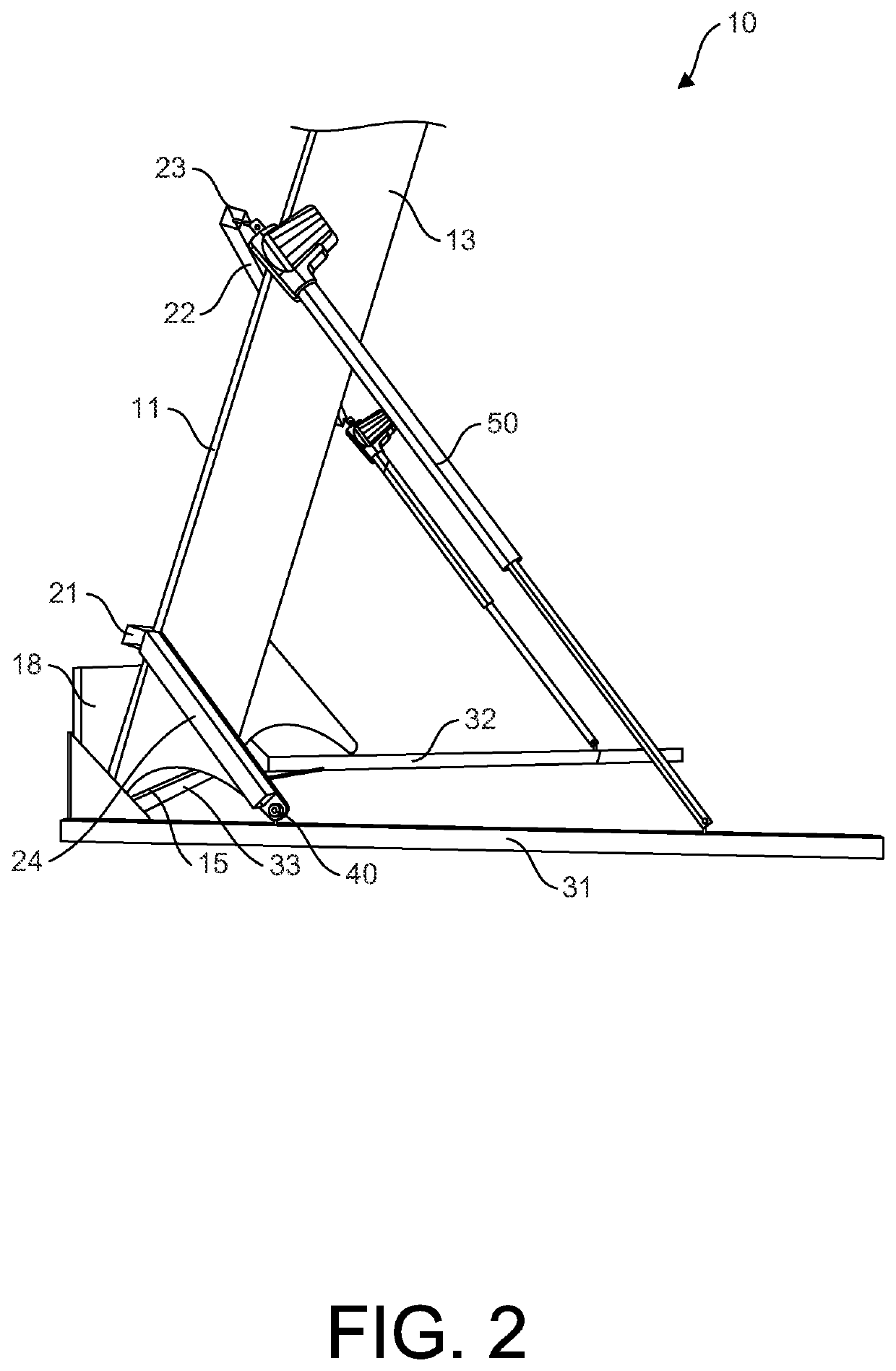
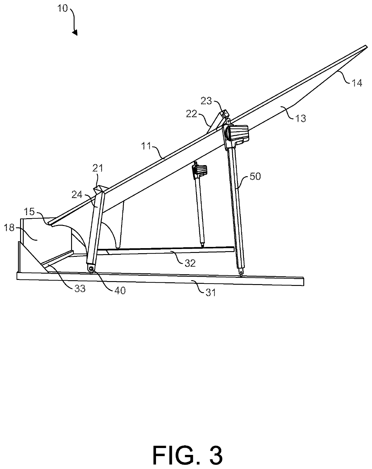
[0030]Embodiments of the present disclosure are directed to an adjustable-incline climbing wall assembly 10.
[0031]Embodiments of the adjustable-incline climbing wall assembly 10 disclosed herein comprise one or more climbing panels 11 containing a plurality of climbing grips 12. The front face(s) of the one or more climbing panels 11 that contains the plurality of climbing grips 12 is known as the climbing surface 13. In some embodiments, the climbing surface 13 may be formed by a single climbing panel 11. In other embodiments, multiple climbing panels 11 may be aligned with one another to form a substantially continuous climbing surface 13. The surface(s) of the one or more climbing panels 11 that make up the climbing surface 13 may be textured or may be smooth. A plurality of climbing grips 12 are affixed to the one or more climbing panels 11 and extend from the climbing surface 13. The plurality of climbing grips 12 may have a variety of configurations, as is generally understood...
PUM
 Abstract
Description
Claims
Application Information