Planar Linkage, Methods of Decoupling, Mitigating Shock and Resonance, and Controlling Agricultural Spray Booms Mounted on Ground Vehicles

a technology of plane linkage and spray boom, which is applied in the direction of shock absorbers, rod connections, couplings, etc., can solve the problems of excessive potential destructive forces generated at the spray boom, speed may have to be reduced, active control response is often considered too slow to fully mitigate movement, etc., to maximize vehicle speed, maximize agricultural sprayer utility, and maximize the effect of vehicle speed

Active Publication Date: 2014-09-18
CNH IND AMERICA LLC
View PDF2 Cites 24 Cited by
  • Summary
  • Abstract
  • Description
  • Claims
  • Application Information

AI Technical Summary

Benefits of technology

[0032]According to one advantage of the present invention, wide-span spray booms of the present invention are designed using lightweight high-strength materials. This allows the boom's span to be maximized while the structural loads, resulting largely from the boom structural mass, can be kept with the limits defined by the operational life requirements. In order to maximize agricultural sprayer utility in terms of area sprayed in unit time that both the boom-span and vehicle speed be maximized; notwithstanding that both these parameters significantly increase the propensity of the boom structure to flexure and resonance. The fatigue strength of the structure in addition to the limit-load strength of the boom structure should be accounted for in a boom design. Accordingly, an advantage of the present invention is that structural resonance, particularly in the vertical and longitudinal vehicle axis directions, can be eliminated or reduced to acceptable levels, particularly at the resonant Eigen-frequencies.
[0033]The resulting fatigue strength and structural strength allow for the booms to have a greater width and the vehicle to travel at a faster speed. This results in greater coverage per unit time.
[0034]According to another advantage of the present invention, the spray boom structure is of the truss or lattice type, so that the vehicle driver's visibility through the structure is not significantly impeded when the booms are in the folded position along both sides of the vehicle.
[0035]A near planar linkage is provided according to one aspect of the present invention. The near planar linkage can carry weights in a plane without the need for direct contact points such as rollers. It is understood that the motion of an object connected to the linkage can be nearly planar.
[0036]According to another advantage of the present invention, the boom system is able to accurately maintain the optimal, near constant, spray height above the ground, and can follow the smooth contours and undulations in the ground surface profile in span at the highest practical vehicle spraying speed.
[0037]According to another advantage of the present invention, methodologies to mitigate otherwise excessive loads from being imposed on the boom's structure and attachments to the vehicle due to the vehicle's angular displacements in roll over uneven ground being reacted against the deployed booms' extremely high polar moments of inertia in roll are provided.

Problems solved by technology

However, when not being used for spraying, these wide-span booms are required to fold away to a stowed position, typically along either side of the vehicle, to permit the vehicle to navigate field entrance gates and traverse tracks, roads or highways, without exceeding either practical or legal width limits.
Accordingly, if the vehicle moves in angular displacement about its roll axis due to continuously varying relative vertical displacements of the wheels at either wheel track, then enormous potentially destructive forces may be generated at the booms' attachments to the center rack, unless some mitigating design features are incorporated to prevent or reduce such forces.
While this has proven to be effective, at least to some extent, the active control response is often considered to be too slow to be fully effective in mitigating the movements and forces caused by sudden roll excursions of the vehicle.
Consequently, over the more undulating surfaces, the vehicle speed may have to be reduced to unacceptably slow levels to allow time for the corrective response to take place, or loss of effective control of the outboard boom section heights may take place, giving rise to unnecessarily high boom forces in roll as well as defective spray application and may even cause the boom tips to impact the ground.
This may well be an improvement, but it is not a full solution since typically outer boom height control is still rendered somewhat ineffective in practice.
In some cases, semi-active control of the longitudinal and yaw accelerations is also currently practiced, while automatically self-leveling the booms relative to the sensed ground position at a pre-set spray height, combined with compliant boom suspension, effectively results in semi-active vertical boom suspension, there still remain some serious deficiencies in structural and fatigue boom design capabilities.
Such resonant vibrations, magnified by an exciting frequency, can rapidly fail or fatigue the boom's structure prematurely.
Further, designing to avoid the critical frequencies generated by the vehicle is largely thwarted by the potentially wide range of frequencies able to be generated due to mass of the vehicle changing on its suspension and tires, as its liquid cargo is discharged during the spraying operation.
This is a significant weakness in contemporary high-spans pray booms, and one which will only become worse as economic necessity drives future spray boom spans wider.
From the foregoing it can be seen that there are a large number of relevant factors that need to be addressed in the optimal design of wide-span spray agricultural booms, and that contemporary designs are deficient in a number of respects.

Method used


Image

  • Planar Linkage, Methods of Decoupling, Mitigating Shock and Resonance, and Controlling Agricultural Spray Booms Mounted on Ground Vehicles
  • Planar Linkage, Methods of Decoupling, Mitigating Shock and Resonance, and Controlling Agricultural Spray Booms Mounted on Ground Vehicles
  • Planar Linkage, Methods of Decoupling, Mitigating Shock and Resonance, and Controlling Agricultural Spray Booms Mounted on Ground Vehicles

Examples


Embodiment Construction

[0083]While the invention will be described in connection with one or more preferred embodiments, it will be understood that it is not intended to limit the invention to those embodiments. On the contrary, it is intended to cover all alternatives, modifications and equivalents as may be included within the spirit and scope of the invention as defined by the appended claims.

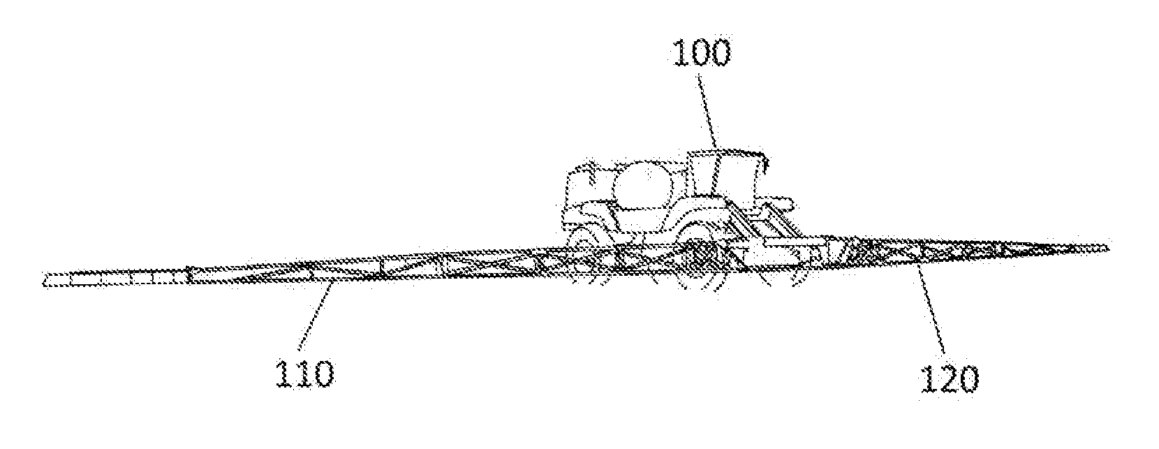
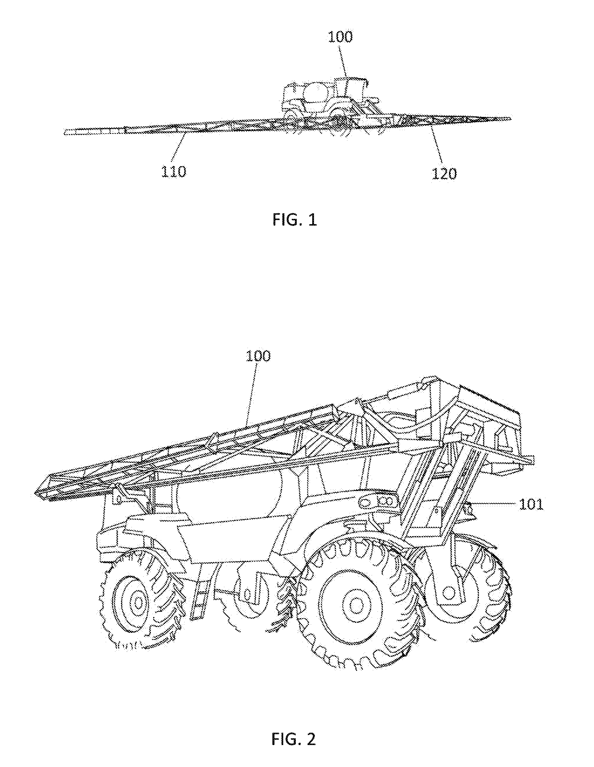
[0084]Referring now to the invention in more detail, FIGS. 1 and 2 show the booms mounted in position on a vehicle. FIG. 1 shows them as they would be in the deployed in the full-span and part-span operating position when used for spraying crops, while FIG. 2 shows the invention in its folded position as it would be used for driving to and from the fields being sprayed, maneuvering through field entrances gates, along tracks or on roads or highways. Unless otherwise noted, the booms 110 and 120 shown in the various embodiments of the current invention comprise three primary identifiable segments: The primary or in...


PUM


Abstract

The current invention discloses several methodologies that mitigate shock loading and propensity to resonance in agricultural spray boom structures. These include a near planar linkage for decoupling the boom assembly from the vehicle. This serves to permit further aspects of the invention to: Use the combined mass of the booms and center section as the tuned mass of a tuned mass damper: Act as an enabling part of a boom compliant suspension system to mitigate shock loadings otherwise imposed on the boom system, and: Act as an enabling part of an active boom height and roll control systems to permit the accurate navigation of the boom over undulating terrain. Further aspects include the incorporation of tuned mass dampers in the boom structure and components; and the use of the mass and operation of the boom outboard “breakaway” sections as tuned mass dampers.

Description

[0001]This United States utility patent application claims priority on and the benefit of provisional application 61 / 794,655 filed Mar. 15, 2013, the entire contents of which are hereby incorporated herein by reference.FIELD OF THE INVENTION[0002]The present invention relates to a planar linkage, to the support, isolation and dynamic control of spray booms connected to a tractor, trailer or other vehicle for the purpose of agricultural spraying and to a gas tension spring.BACKGROUND OF THE INVENTION[0003]Agricultural fields are often sprayed with various spraying solutions, such as herbicides, insecticides, fertilizers, etc. Sprayers for this purpose are required to have a wide span booms furnished with plumbing and multiple spray nozzles, for the liquids being sprayed, at defined intervals across the boom's span: While contemporary span widths may extend as wide as 120 through to 162 feet, with even wider spans predicted in the future. However, when not being used for spraying, the...

Claims


Application Information

Patent Timeline
Patent Type & Authority Applications(United States)
IPC IPC(8): A01G25/09F16F9/02F16C11/04
CPCA01G25/09F16F9/0209F16C11/04A01M7/0053Y10T403/32008A01M7/0078F16F9/02F16F9/38A01C23/047F16F7/104
Inventor VENTON-WALTERS, ROY
Owner CNH IND AMERICA LLC
Why Eureka
Try Eureka