Liquid Discharge Apparatus, Head Unit and Mist Collector

a liquid discharge apparatus and head unit technology, applied in the direction of printing, other printing apparatus, etc., can solve the problems of adhesion of mist, and achieve the effect of reducing the adhesion of mist and reducing the flow of liquid down

Active Publication Date: 2022-02-10
BROTHER KOGYO KK
View PDF0 Cites 0 Cited by
  • Summary
  • Abstract
  • Description
  • Claims
  • Application Information

AI Technical Summary

Benefits of technology

[0007]In view of such a situation, an object of the present disclosure is to provide a liquid discharge apparatus and a head unit which are capable of lowering any adhesion of the mist to the UV light irradiating part. Further, another object of the present disclosure is to provide a liquid discharge apparatus and a mist collector which are capable of reducing a liquid flowing down from the mist collector.

Problems solved by technology

Due to this, there is such a fear that any mist which is not caught by the mist catching part and flows out of the mist catching part might flow to a side of the UV light irradiator and might adhere to the UV light irradiator.
Due to this, there is such a fear that the adhered mist might aggregate, whereby the ink might flow down along the inner wall and might dirty a recording medium, etc.

Method used


Image

  • Liquid Discharge Apparatus, Head Unit and Mist Collector
  • Liquid Discharge Apparatus, Head Unit and Mist Collector
  • Liquid Discharge Apparatus, Head Unit and Mist Collector

Examples


first embodiment

[0017]In the following, a first embodiment of the present disclosure will be specifically explained, with reference to the drawings. Note that in the following description, same reference numerals are affixed to same or corresponding elements throughout all the drawings, and any overlapping explanation therefor will be omitted.

Configuration of Liquid Discharge Apparatus

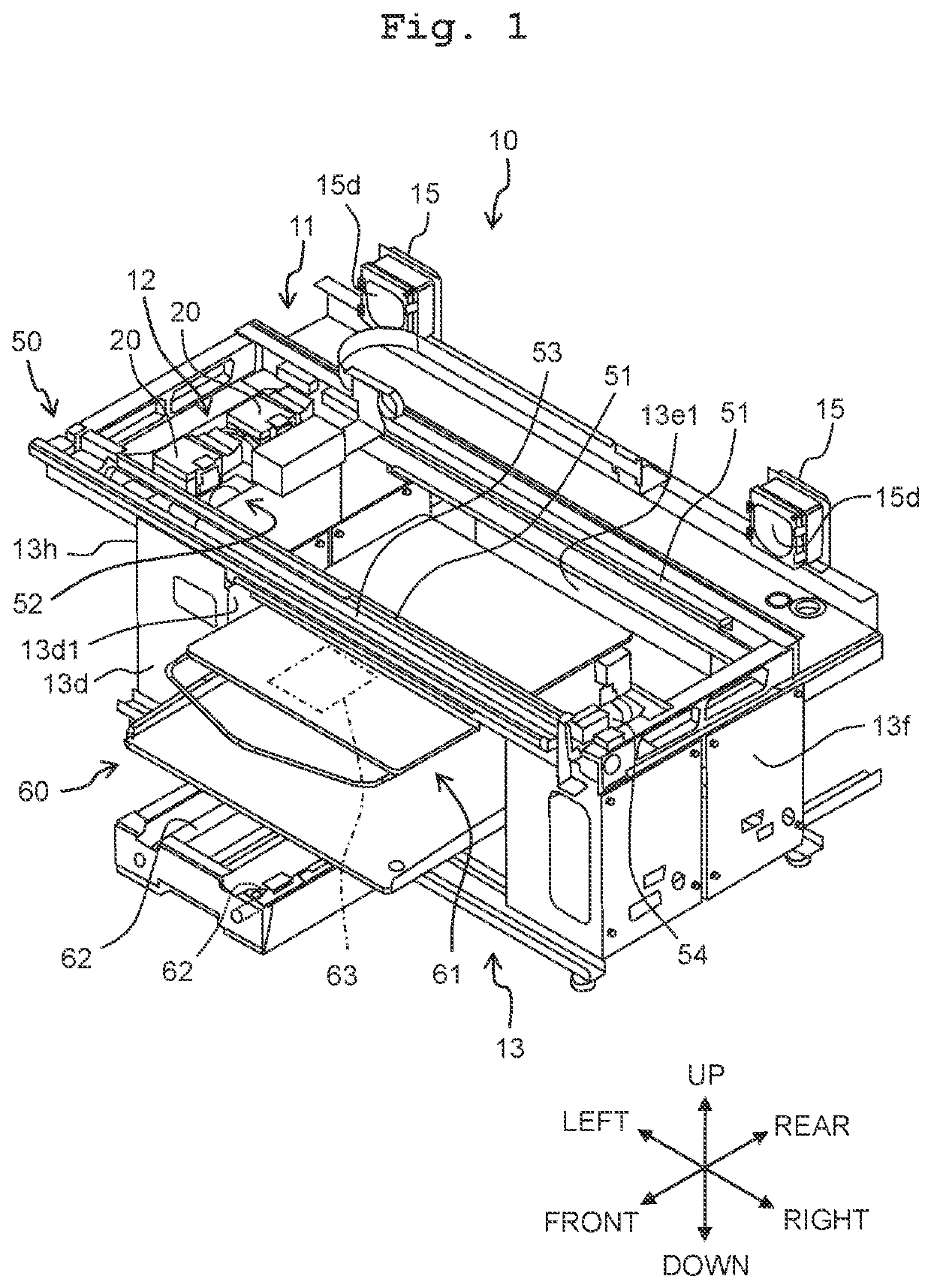
[0018]A liquid discharge apparatus 10 according to an embodiment of the present disclosure is, for example, an ink-jet printer which discharges or ejects a liquid such as an ink, etc., from a head 20 onto a medium A (FIG. 4) so as to print an image on the medium A, as depicted in FIGS. 1 and 2. The medium A is exemplified, for example, by a sheet such as fabric, paper, etc., and a three-dimensional object such as a ball, a mug, etc. The liquid discharge apparatus 10 is provided with a casing 11, a head unit 12, a scanning device 50, a conveying device 60 and a controller 70 (FIG. 3). Note that the detail of the contro...

first modification

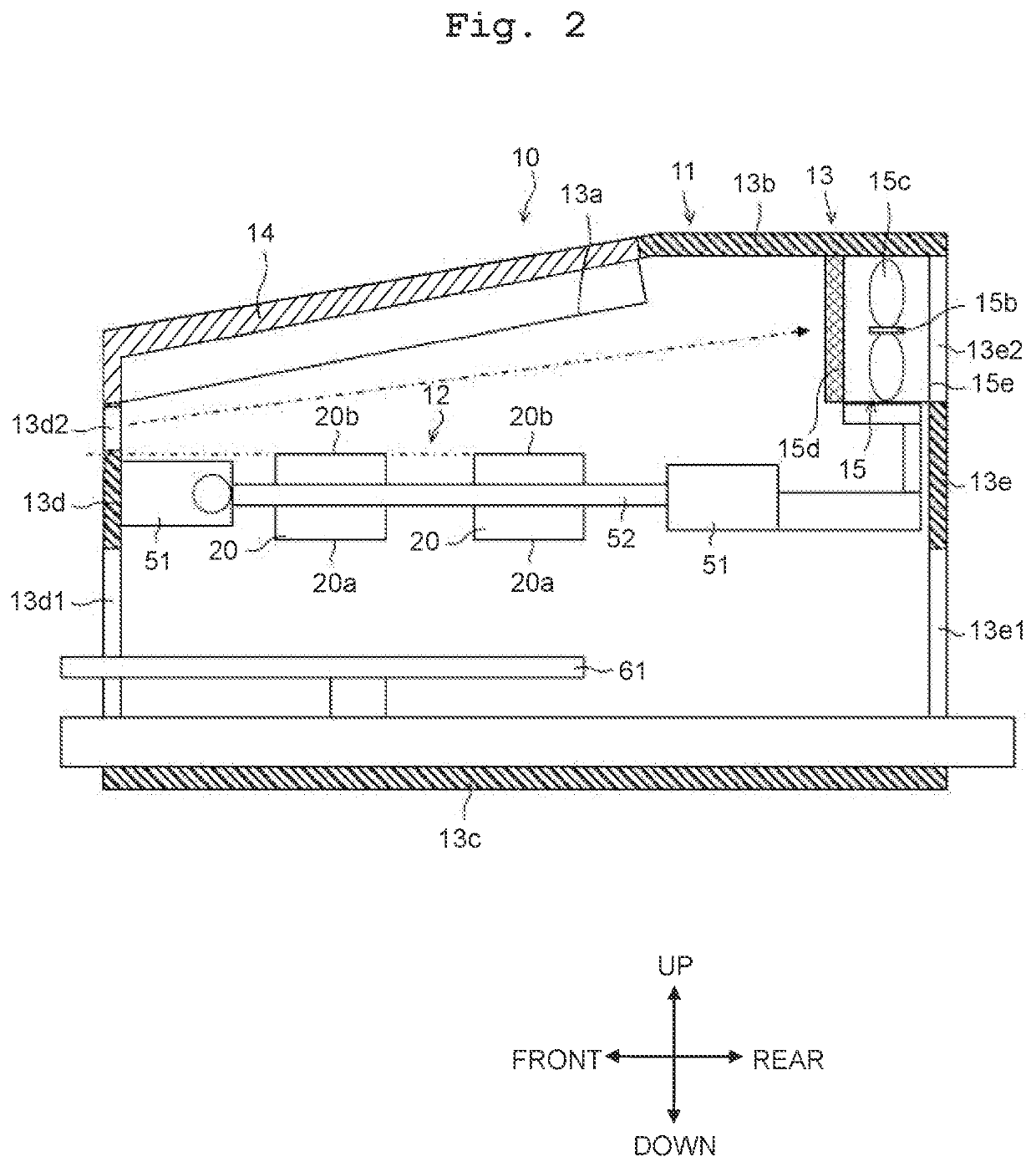
[0123]A liquid discharge apparatus 10 according to a first modification is provided with a casing 11 accommodating the head 20, the fixing device 30 and the mist collector 40 therein, in the liquid discharge apparatus 10 of the above-described embodiment, and having an intake port 13d2 via which an outside air is taken into the casing 11. The head 20 has a discharge surface 20a, and an end surface (upper end surface 20b) on a side opposite to the side of the discharge surface 20a in the second direction. The intake port 13d2 is arranged, in the second direction, on the side opposite to the discharge surface 20a with respect to the end surface (upper end surface 20b).

[0124]Specifically, as depicted in FIG. 2, one or a plurality of pieces of the intake port 13ds is / are opened in a first wall 13d of the casing 11, in addition to a front port 13d1. The front port 13d1 is arranged at a location below the discharge surface 20a of the head 20. The intake port 13d2 is arranged at a location...

second modification

[0126]In a liquid discharge apparatus 10 according to a second modification, the casing 11 in the liquid discharge apparatus 10 according to the first modification has: a first wall 13d in which an intake port 13d2 is arranged, and a second wall 13e which is located on an opposite side to the first wall 13d, with the fixing device 30 and the mist collector 40 being interposed therebetween. The second wall 13e has a release port 13e2 via which the air is released to outside of the second wall 13e. The casing 11 is provided with a third fan 15 configured to release the air via the release port 13e2.

[0127]Specifically, as depicted in FIG. 2, the second wall 13e is arranged at a location on the rear side with respect to the first wall 13d, and arranged to be parallel to the first wall 13d. In the front-rear direction, the head 20, the fixing device 30 and the mist collector 40 are arranged between the first wall 13d and the second wall 13e in the front-rear direction. In the second wall...


PUM


Abstract

There is provided a liquid discharge apparatus including: a head, a fixing device and a mist collector configured to collect a mist of a liquid. The mist collector and the fixing device are arranged side by side in this order in a first direction. The mist collector is provided with an air channel having a suction port and an exhaust port. The air channel has: a first part and a second part connected to an other end of the first part. The exhaust port is opened, in the second part, toward any one of directions which are: a direction including a direction opposite to the first direction as a directional component thereof, a third direction orthogonal to the first direction and a second direction, and a direction opposite to the third direction.

Description

CROSS REFERENCE TO RELATED APPLICATION[0001]The present application claims priorities from Japanese Patent Applications No. 2020-132971, filed on Aug. 5, 2020 and No. 2020-132972, filed on Aug. 5, 2020, the disclosures of which are incorporated herein by reference in their entireties.BACKGROUNDField of the Invention[0002]The present disclosure relates to a liquid discharge apparatus, a head unit and a mist collector.Description of the Related Art[0003]As an example of a liquid discharge apparatus, there is known an image forming apparatus. In a certain publicly known image forming apparatus, an ink-jet recording head, a mist catching part and an UV light irradiator are arranged to be side by side in this order. An ink is made to fly from the ink-jet recording head onto a recording medium, and the ink on the recording medium is irradiated with an UV light by the UV light irradiator, thereby curing the ink. Further, a mist of the flying ink is caught by the mist catching part.[0004]Fu...

Claims


Application Information

Patent Timeline
Patent Type & Authority Applications(United States)
IPC IPC(8): B41J2/17B41J29/377
CPCB41J2/1714B41J29/377B41J29/38B41J29/02B41J29/13B41J2/17563B41J2/475
Inventor KOBAYASHI, AKIHIROTAKEDA, KENGONISHIMOTO, TAKAHIRO
Owner BROTHER KOGYO KK
Why Eureka
Try Eureka