Suture cutting devices

a technology of suture cutting and suture, which is applied in the field of suture cutting devices, can solve the problems of increasing recovery time, unsuitable access to tissue in this manner, and particularly challenging suture of tissue, and achieves the effect of low profile shap

Pending Publication Date: 2022-03-03
CETERIX ORTHOPAEDICS
View PDF0 Cites 0 Cited by
  • Summary
  • Abstract
  • Description
  • Claims
  • Application Information

AI Technical Summary

Benefits of technology

[0006]The devices and methods described herein can be used to cut sutures during a medical procedure, such as during arthroscopic procedures. The suture cutting devices can have a low profile shape for accessing regions within the body with limited space like joints, such as the knee or shoulder. The suture cutting devices can include a cutter (also referred to as a blade) having an end with a cutting edge. In some cases, the cutter has a hollow (e.g., tubular) shape to accommodate a component, such as a holding tube used to secure the suture. The cutter may be rotatable and / or axially translatable for cutting the suture. The rotation and axial translation of the cutter may be separately or simultaneously executed. The suture cutting devices may be configured to push the knot within the suture and secure the suture for cutting near the knot.
[0007]According to some embodiments, a suture cutting device includes a handle and an elongate holding tube attached to the handle. The holding tube can include a slot configured to allow a suture to pass into the holding tube. The suture cutting device can include an inner mandrel within the holding tube. The inner mandrel can be configured to move relative to the holding tube to capture the suture in a channel between the inner mandrel and the holding tube. The suture cutting device can include a cutter around the holding tube. The cutter can be configured to rotate relative to the holding tube such that a cutting edge of the cutter cuts the suture when captured within the channel. The suture cutting device can include an actuator arranged to control rotation of the cutter for cutting the suture.
[0008]In some cases, the cutter is configured to move axially relative to the holding tube for cutting the suture. The cutter may be configured to simultaneously rotate and move axially. The cutter may be configured to separately rotate and move axially. The actuator may be configured to control rotation and axial movement of the cutter. The actuator may be configured to be activated in at least two modes, wherein activating the actuator in a first mode causes the cutter to rotate and activating the actuator in a second mode causes the cutter to move axially. Activating the actuator in the first mode can include rotating the actuator, and activating the actuator in the second mode can include translating the actuator. In some cases, the suture cutting device includes at least two actuators. For example, a first actuator can be configured to control rotation of the cutter and a second actuator can be configured to control axial movement of the cutter. The actuator may be configured to rotate the cutter in a first direction when the actuator is activated and rotate the cutter in a second direction when the actuator is released. The device can further include a cutter release configured to prevent rotation and / or axial motion of the cutter unless the cutter release is disengaged. The cutter can be operationally coupled with a gear assembly that is configured to rotate and / or axially translate the cutter. The gear assembly can include a spring configured to bias the cutter axially in a distal direction relative to the handle. The gear assembly can include a second spring configured to bias the cutter axially in a proximal direction relative to the handle. The gear assembly can include at least a first gear operationally engaged with a second gear. For example, the first gear can be coupled to the cutter and the second gear can be coupled to the actuator. The first gear may share a rotational axis with the cutter. The actuator can include a slider that translates distally and / or proximally relative to the holding tube, wherein the second gear is configured to rotate in response to translation of the actuator. The actuator may be located anywhere on the suture cutting device. For example, the actuator can be on the on the handle. The actuator can include any type of actuator (also referred to as a control). For instance, the actuator can include one or more of a button, a translatable member, a turnable member or a rotatable member. The actuator can include one or more of a pushable button, a pullable button, a slider, a toggle, a knob, a lever, a trigger or a wheel. The suture cutting device can also include a lock coupled to the inner mandrel and configured to prevent axial movement of the inner mandrel until the lock is released. The lock can be configured to be released by the operation of the actuator. The inner mandrel can be axially movable relative to the holding tube. The holding tube can be configured to capture the suture between the notch of the inner mandrel and the holding tube when the inner mandrel is extended distally. The actuator may be configured to control axial motion of the inner mandrel. In some instances, the actuator is configured to be operated with a single finger. The cutter may be operationally coupled to a cam assembly that is configured to rotate and / or axially translate the cutter. In some cases, the rotation and / or axially translation of cutter is at least partially defined by a guide path. The guide path can include a channel in the cutter or connected to the cutter. The guide path can include a channel in or on the actuator. The inner mandrel may rotate with respect to the holding tube to capture the suture. The inner mandrel may rotate with respect to the holding tube to capture the suture. The inner mandrel may be configured to rotate without axially moving with respect to the holding tube. The inner mandrel may rotate without axially moving with respect to the holding tube to capture the suture. The inner mandrel rotates without axially moving distally with respect to the holding tube.

Problems solved by technology

Suturing of tissue can be particularly challenging in difficult to access body regions and regions that have limited clearance, such as regions partially surrounded or covered by bone.
However, in many cases, accessing the tissue in this manner is undesirable, increasing recovery time, and exposing the patient to a greater risk of infection.
Generally, these devices are small in size and have low profiles for entering the body and navigating between soft tissues and bone.
In some cases, the small size constraints for these devices have an impact on the functioning of the devices.
For instance, it can be difficult to provide the necessary forces to cut sutures in confined spaces without damaging closely surrounding tissues.

Method used


Image

  • Suture cutting devices
  • Suture cutting devices
  • Suture cutting devices

Examples


Embodiment Construction

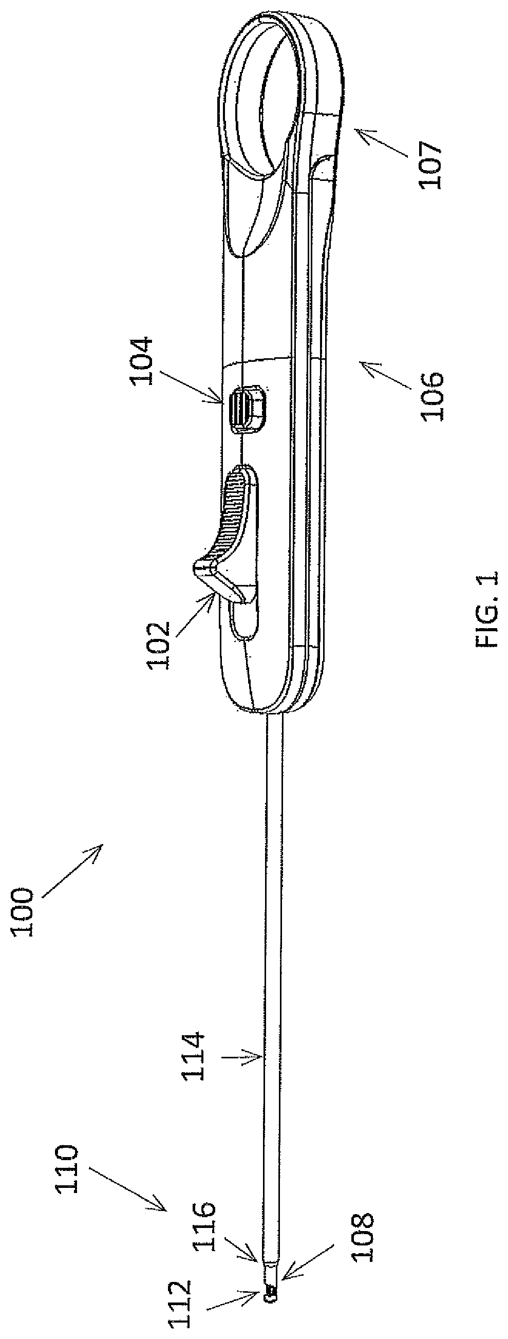
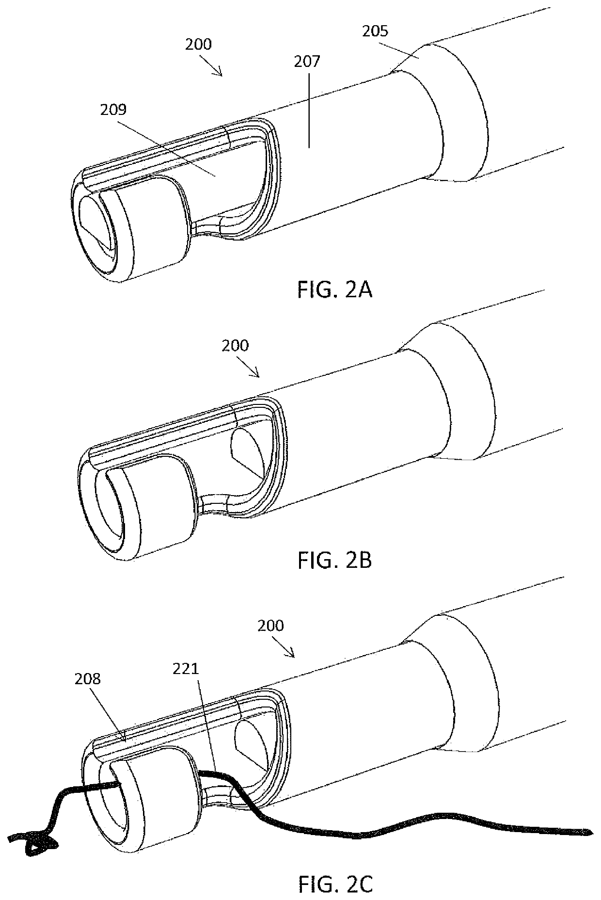
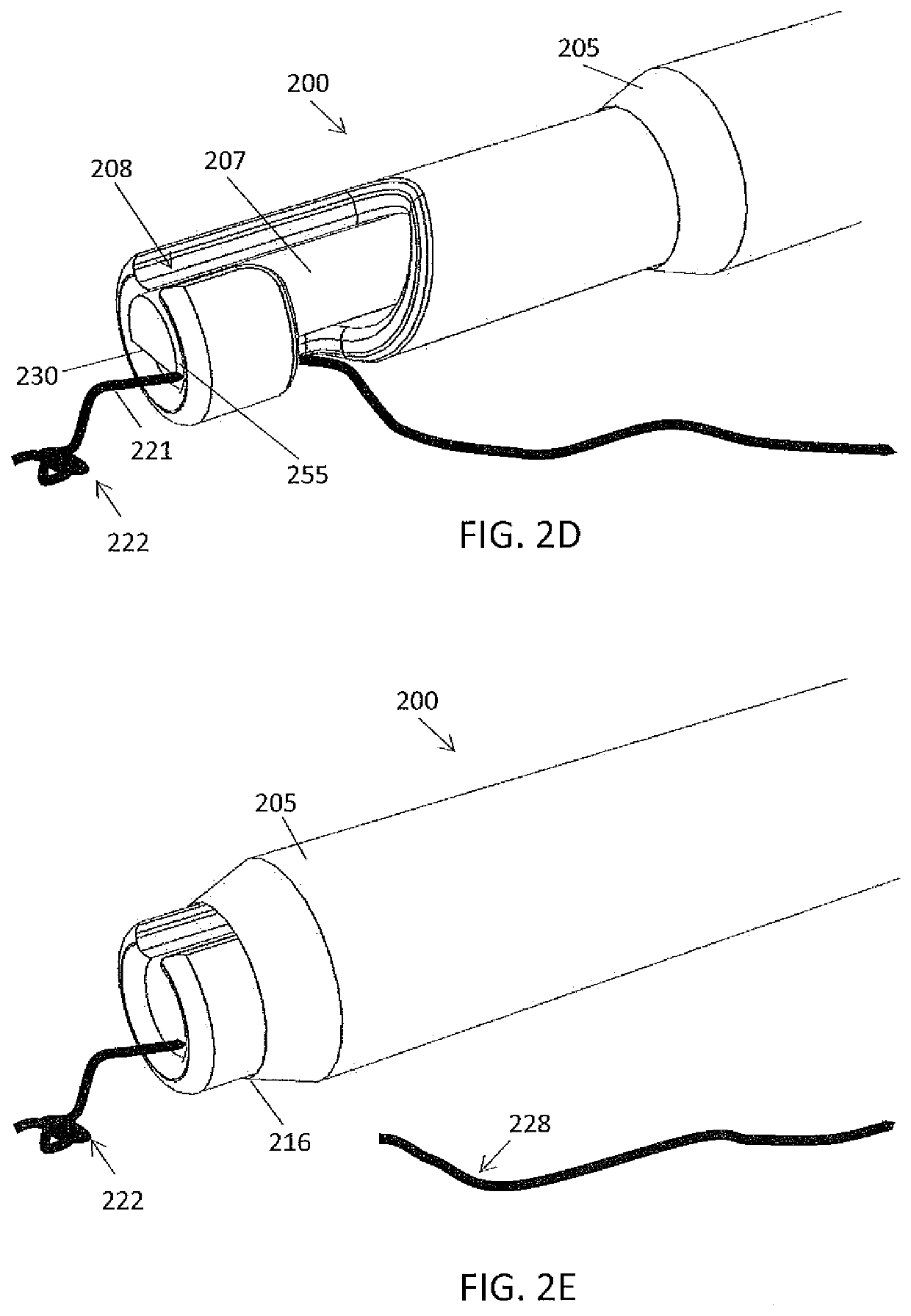
[0037]Devices and methods described herein can be used to cut sutures in a patient during a medical procedure. The devices can be shaped and sized to access confined regions of the body, such as joint areas (e.g., knees, shoulders, etc.). The devices can include an elongate holding tube and a cutter that at least partially surrounds the holding tube and that is configured to cut the suture after suturing of a body tissue. The cutter can be configured to rotate with respect to the holding tube to cut the suture. Additionally or alternatively, the cutter can be configured to advance distally with respect to the holding tube to cut the suture. In some embodiments, the devices can additionally be used to push a pre-tied knot within the suture to cinch the knot in a desired location, such as a repair site. The devices can also include an inner mandrel within the holding tube, which cooperates with the holding tube to secure the suture during the cutting. In some cases, the inner mandrel ...


PUM


Abstract

Suture cutting devices to be used arthroscopically, for example, in an arthroscopic knee surgery may be operated with a control for rotating a cutter to cut a suture, for example, once a knot is placed in the suture. The rotatable cutter may also be configured to axially translate during a suture cutting procedure. The rotation and axial translation of the cutter may be separately or simultaneously executed. The suture cutting devices may be configured to push the knot within the suture and secure the suture for cutting near the knot. The suture cutting devices may include a holding tube and mandrel for securing the suture, for example, prior to cutting.

Description

CROSS REFERENCE TO RELATED APPLICATION[0001]This application is a U.S. National Phase Entry of PCT Application Serial No. PCT / US20 / 012876 filed Jan. 9, 2020 and titled “SUTURE CUTTING DEVICES”, which claims priority to U.S. Patent Application No. 62 / 792,053, entitled “SUTURE CUTTING DEVICES”, filed Jan. 14, 2019. This application may be related to U.S. Provisional Patent Application No. 61 / 881,319, entitled “ARTHROSCOPIC KNOT PUSHER AND SUTURE CUTTER,” filed on Sep. 23, 2013; U.S. Pat. No. 9,247,935, entitled “ARTHROSCOPIC KNOT PUSHER AND SUTURE CUTTER,” issued on Feb. 2, 2016; U.S. Pat. No. 9,332,980, entitled “ARTHROSCOPIC KNOT PUSHER AND SUTURE CUTTER,” issued on May 10, 2016; U.S. patent application Ser. No. 16 / 208,526, entitled “ARTHROSCOPIC KNOT PUSHER AND SUTURE CUTTER,” filed on Dec. 3, 2018; and U.S. Pat. No. 10,143,464, entitled “ARTHROSCOPIC KNOT PUSHER AND SUTURE CUTTER,” issued on Dec. 4, 2018, each of which is incorporated herein in its entirety by reference.INCORPORAT...

Claims


Application Information

Patent Timeline
Patent Type & Authority Applications(United States)
IPC IPC(8): A61B17/04
CPCA61B17/0467A61B2017/00367
Inventor PETER, STEPHEN J.QUITUGUA, VICTORIA C.TAGGARD, JOSHUA D.BENDER, CHRISTOPHER P.HIROTSUKA, MARK Y.HENDRICKSEN, MICHAEL J.
Owner CETERIX ORTHOPAEDICS
Why Eureka
Try Eureka