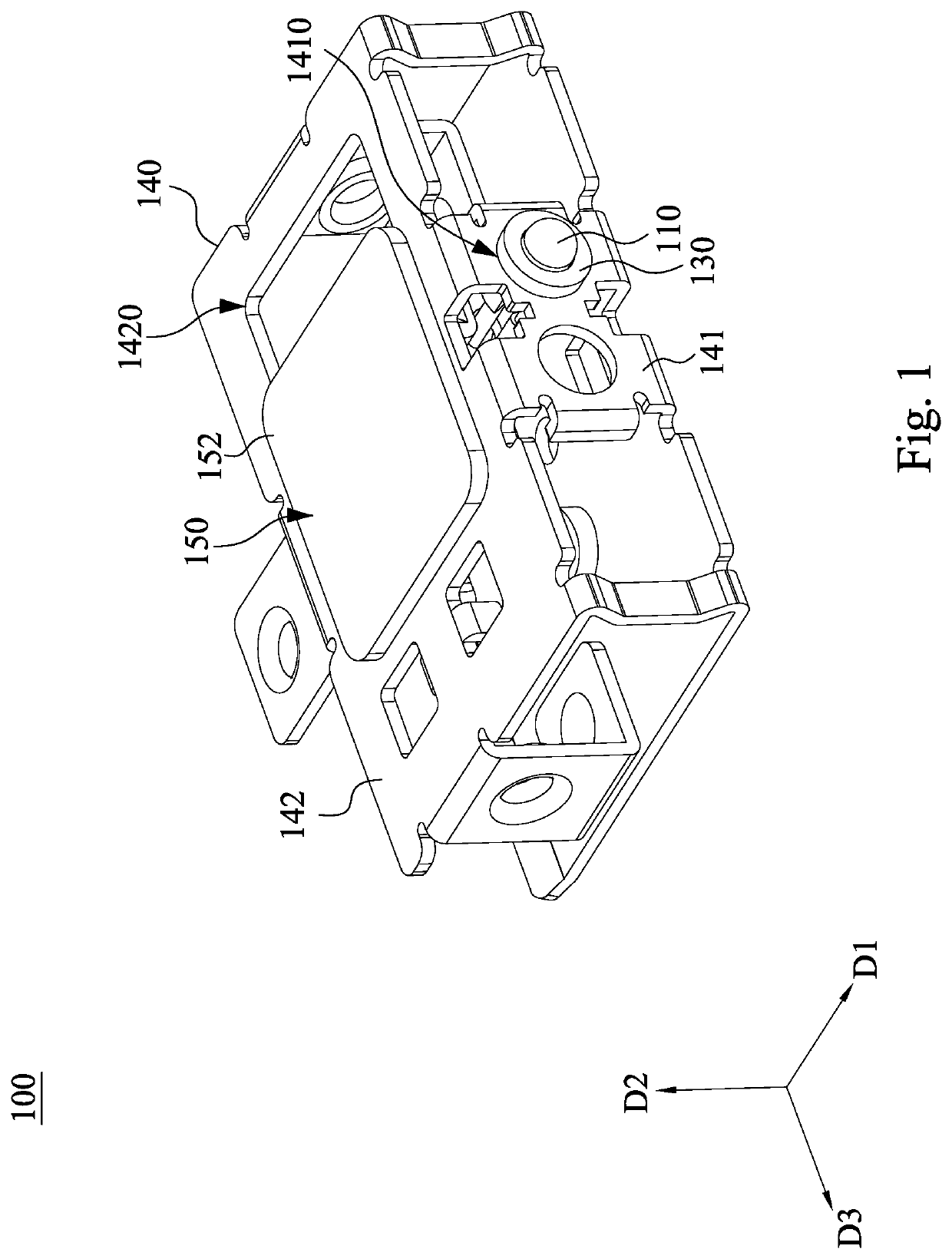
Assembly structure

a technology of assembly structure and light-emitting diode element, which is applied in the direction of casings/cabinets/drawers, instruments, casings/cabinets/drawers, etc., can solve the problems of uneven brightness appearance, and achieve the effect of further restricting the spatial displacement of light-emitting diode element 110 and improving the problem of light appearance difference caused by rotation

Active Publication Date: 2022-03-10
INVENTEC PUDONG TECH CORPOARTION +1
View PDF3 Cites 0 Cited by
  • Summary
  • Abstract
  • Description
  • Claims
  • Application Information

AI Technical Summary

Benefits of technology

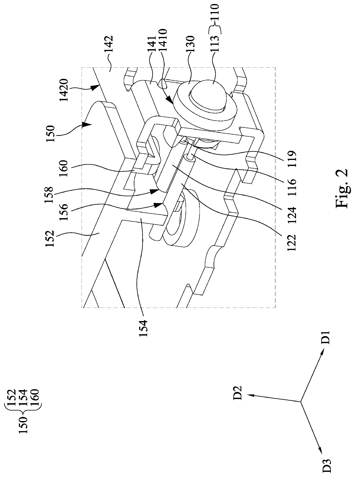
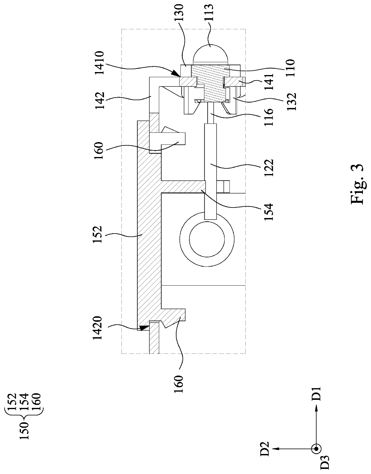
[0057]In FIG. 6B, the engaging member 136 and the opposite engaging member 139 are arranged along the direction D3, and the direction D3 is perpendicular to the direction D2 in which the convex member 154 of the limiting member 150 extends. In other words, the direction D3 in which the engaging member 136 is opposite to the engaging member 139 is perpendicular to the direction D2 in which the convex member 154 of the limiting member 150 extends. The engaging member 136 and the opposite engaging member 139 arranged along the direction D3 can further make the first abutting portion 156 and the second abutting portion 158 on the convex member 154 restrict the pin 116 and the pin 119, which extend along the direction D1. Therefore, the spatial displacement of the light-emitting diode element 110 can be further restricted.
[0058]In summary, the present disclosure provides an assembly structure. The rotation of the working element to be fixed to the housing can be restricted through the pins of the working element limited by a limiting member, and the degree of freedom of the working element in the rotational direction can be restricted. Therefore, if the working element is a light-emitting diode element, the problem of light appearance difference caused by rotation can be improved, and the uniformity of the brightness of the light-emitting diode element is maintained and is not affected by the assembly angle problem.

Problems solved by technology

If, after assembly, the angle of the light-emitting diode is different from a predetermined assembly angle, the brightness appearance would not be uniform.

Method used


Image

  • Assembly structure
  • Assembly structure
  • Assembly structure

Examples


Embodiment Construction

[0026]The following embodiments are disclosed with accompanying diagrams for detailed description. For illustration clarity, many details of practice are explained in the following descriptions. However, it should be understood that these details of practice do not intend to limit the present disclosure. That is, these details of practice are not necessary in parts of embodiments of the present disclosure. Furthermore, for simplifying the drawings, some of the conventional structures and elements are shown with schematic illustrations. Also, the same labels may be regarded as the corresponding components in the different drawings unless otherwise indicated. The drawings are drawn to clearly illustrate the connection between the various components in the embodiments, and are not intended to depict the actual sizes of the components.

[0027]In addition, terms used in the specification and the claims generally have the usual meaning as used in the field, in the context of the invention a...


PUM


Abstract

An assembling structure includes a working element, a housing and a limiting member. The working element includes first and second pins. The housing includes an opening. The working element is located in the opening. The first and second pins of the working element extend toward an interior of the housing. The limiting member is connected to the housing. The limiting member includes a supporting plate and a convex member. The convex member includes a first abutting portion and a second abutting portion. The first pin and the second pin respectively abut against the first abutting portion and the second abutting portion.

Description

RELATED APPLICATIONS[0001]This application claims priority to China Application Serial Number 202010921776.2, filed Sep. 4, 2020, which is herein incorporated by reference in its entirety.BACKGROUNDField of Invention[0002]The present disclosure relates to an assembly structure.Description of Related Art[0003]In a conventional shaft-hole assembly, the housing, the holder and the working element to be fixed lack a positioning limitation in a rotational direction. The working element may be a light-emitting diode. If, after assembly, the angle of the light-emitting diode is different from a predetermined assembly angle, the brightness appearance would not be uniform.[0004]Therefore, those in the industry are endeavoring to provide a solution for the above-mentioned problem.SUMMARY[0005]An aspect of the present disclosure relates to an assembly structure.[0006]According to one embodiment of the present disclosure, an assembling structure includes a working element, a housing and a limit...

Claims


Application Information

Patent Timeline
Patent Type & Authority Applications(United States)
IPC IPC(8): H05K5/02
CPCH05K5/0217G06F1/182F21K9/90F21V19/0015F21V23/00F21Y2115/10G06F1/181G06F1/1633
Inventor HUANG, PIN-SHENG
Owner INVENTEC PUDONG TECH CORPOARTION
Why Eureka
Try Eureka