Tooth mug structure for placing toothbrush

a technology for toothbrushes and mugs, applied in the field of tooth mug structures, can solve problems such as reduced practicability, and achieve the effect of effective enhancement of usability

Inactive Publication Date: 2022-03-24
CHOU WEN CHUN
View PDF0 Cites 0 Cited by
  • Summary
  • Abstract
  • Description
  • Claims
  • Application Information

AI Technical Summary

Benefits of technology

[0005]Another object of the present invention is to provide a tooth mug structure for placing toothbrush, the usability is enhanced effectively, and it is unnecessary to find a place for hanging the toothbrush.
[0006]The problem to be solved by the present invention, as conventional tooth brushing appliances are nothing else but tooth mug and toothbrush, in order to make the residual water flow out after tooth brushing, the tooth mug is inverted, so that the internal water flows out to keep the mug dry and sanitary. However, the conventional tooth mug does not have a structure for fixing the toothbrush, the user has to find a hook for hanging the toothbrush, that is inconvenient, and the tooth mug and toothbrush are separate, it frequently happens that one cannot find the toothbrush or takes other's toothbrush, the practicability is reduced greatly.
[0012]In comparison to prior art, with this structure, a first opening and an extended first storage space are disposed on one side inside the upper end of main body, and a second opening, an extended second storage space and a through hole are disposed inside the lower end of main body, so that the first storage space with the first opening in the upper end of main body holds water for rinsing mouth, the second storage space with the second opening in the lower end holds the toothbrush when the main body is inverted, the usability is enhanced effectively, and it is unnecessary to find a place for hanging the toothbrush, meeting the progressiveness, utility and users' needs, its gain is obvious.

Problems solved by technology

However, the conventional tooth mug does not have a structure for fixing the toothbrush, the user has to find a hook for hanging the toothbrush, that is inconvenient, and the tooth mug and toothbrush are separate, it frequently happens that one cannot find the toothbrush or takes other's toothbrush, the practicability is reduced greatly.

Method used


Image

  • Tooth mug structure for placing toothbrush
  • Tooth mug structure for placing toothbrush
  • Tooth mug structure for placing toothbrush

Examples


Embodiment Construction

[0019]The present invention is described with attached figures and embodiments for the reviewer to understand the technical features, content and advantages and effects of the present invention, wherein the figures are merely schematic and supplementary, not the actual scale or accurate configuration of the present invention, so the scale and configuration relationships of the attached figures shall not limit the scope of patent of the present invention in actual implementation.

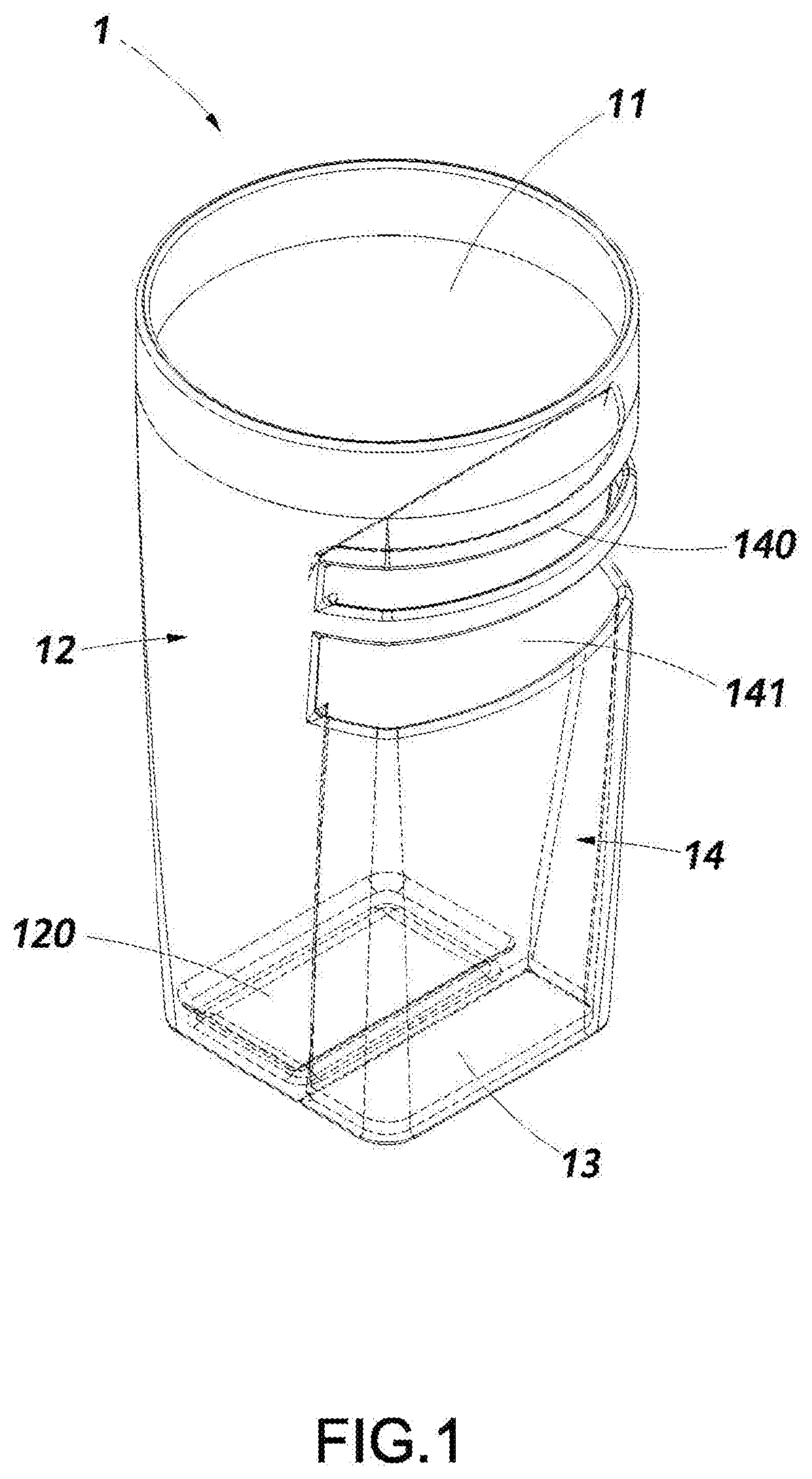
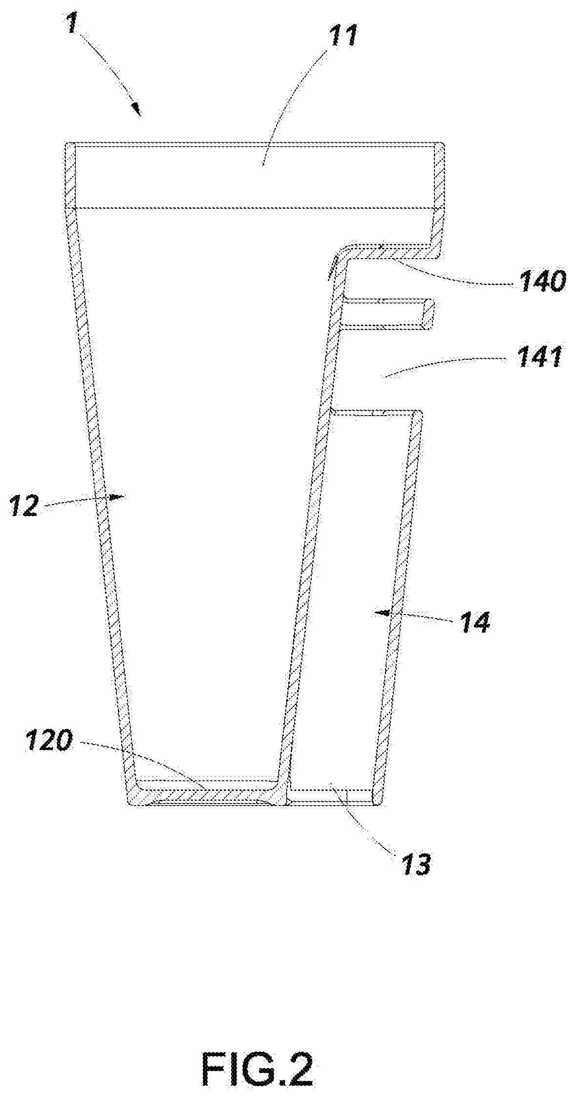
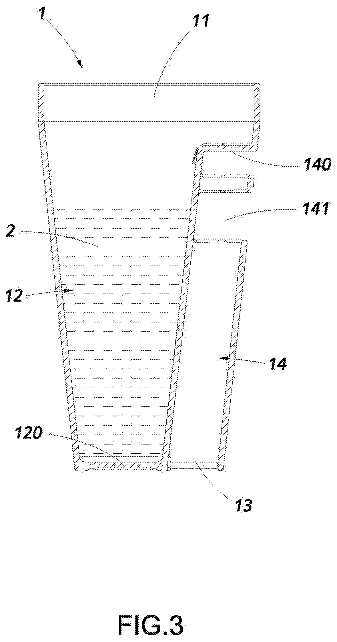
[0020]FIGS. 1 and 2 are the three-dimensional combined diagram and combined profile of the present invention. In a preferred embodiment, the tooth mug structure for placing toothbrush of the present invention comprises a main body 1 and a second opening 13.

[0021]A first opening 11 is disposed on one side inside the upper end of the aforesaid main body 1, a first holding space 12 with a bottom 120 extends from the first opening 11 to the lower end of main body 1.

[0022]The second opening 13 is disposed inside t...


PUM


Abstract

A tooth mug structure for placing toothbrush comprises a main body, a first opening is disposed on one side inside its upper end, a first holding space with a bottom extends from the first opening to the lower end of main body; a second opening, disposed inside the lower end of main body and near the bottom of the first storage space, a second storage space with a bottom extends from the second opening to the upper end of main body; the second storage space of the second opening is provided with at least a through hole; the first opening of the main body is provided with an inclined concave surface for the main body to tilt and stand on three points. This structure enhances the usability effectively, and it is unnecessary to find a place for hanging the toothbrush.

Description

BACKGROUND OF INVENTION1. Field of the Invention[0001]The present invention relates generally to a tooth mug structure, and more particularly to a tooth mug structure for placing toothbrush with a first opening and an extended first storage space on one side inside the upper end of main body, as well as a second opening, an extended second storage space and a through hole inside the lower end of main body.2. Description of Related Art[0002]General tooth brushing appliances are nothing else but tooth mug and toothbrush. The tooth mug is used only for loading water, in order to make the residual water flow out after tooth brushing, the tooth mug is usually inverted to make the internal water flow out to keep the mug dry and sanitary. However, the conventional tooth mug does not have a structure for fixing toothbrush, the user has to find a hook to hang the toothbrush, that is inconvenient, and the tooth mug and toothbrush are separate, one sometimes fails to find the toothbrush or tak...

Claims


Application Information

Patent Timeline
Patent Type & Authority Applications(United States)
IPC IPC(8): A47K1/09
CPCA47K1/09
Inventor CHOU, WEN-CHUN
Owner CHOU WEN CHUN
Why Eureka
Try Eureka