Coil component

a coil and component technology, applied in the direction of transformer/inductance details, fixed inductances, inductances, etc., can solve the problem that the adhesive area cannot be reserved, and achieve the effect of reducing magnetic resistance, increasing fixation, and shortening the length of the magnetic path

Pending Publication Date: 2022-04-07
MURATA MFG CO LTD
View PDF0 Cites 0 Cited by
  • Summary
  • Abstract
  • Description
  • Claims
  • Application Information

AI Technical Summary

Benefits of technology

[0024]According to the embodiment described above, the length of a magnetic path is shortened, thus allowing an inductance value to be larger.
[0025]According to a coil component o

Problems solved by technology

However, when an adhesive is disposed on a wire as described in Japanese Unexamined Patent Application Publication No. 2

Method used


Image

  • Coil component
  • Coil component
  • Coil component

Examples


first embodiment

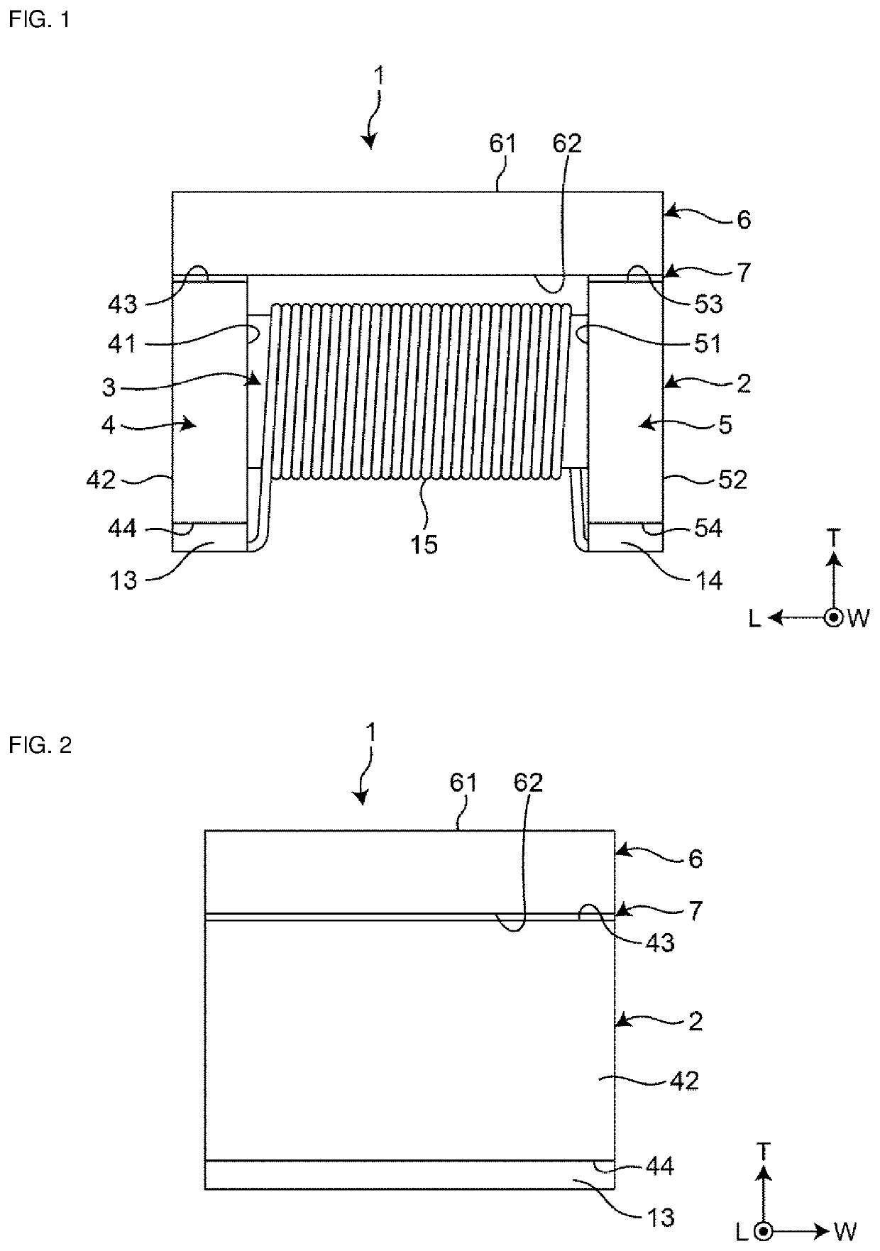
[0036]FIG. 1 is a front view showing a coil component 1 according to a first embodiment of the present disclosure, and FIG. 2 is a side view in which the coil component 1 is seen in a direction toward a first flange portion.

[0037]As shown in FIGS. 1 and 2, the coil component 1 has a core 2, a plate member 6, and an adhesive portion 7 which adheres the core 2 to the plate member 6.

[0038]The core 2 has a winding core portion 3, a first flange portion 4 which is disposed on a first end portion of the winding core portion 3, and a second flange portion 5 which is disposed on a second end portion of the winding core portion 3. The core 2 is formed of a magnetic substance such as ferrite, for example.

[0039]The first flange portion 4 has an inner face 41 which faces the winding core portion 3, an outer face 42 which faces the opposite side to the inner face 41, an upper face 43 which connects the inner face 41 to the outer face 42, and a lower face 44 which faces the opposite side to the u...

examples

[0066]Examples of the present disclosure will be described below, but the present disclosure is not limited to the following description.

second embodiment

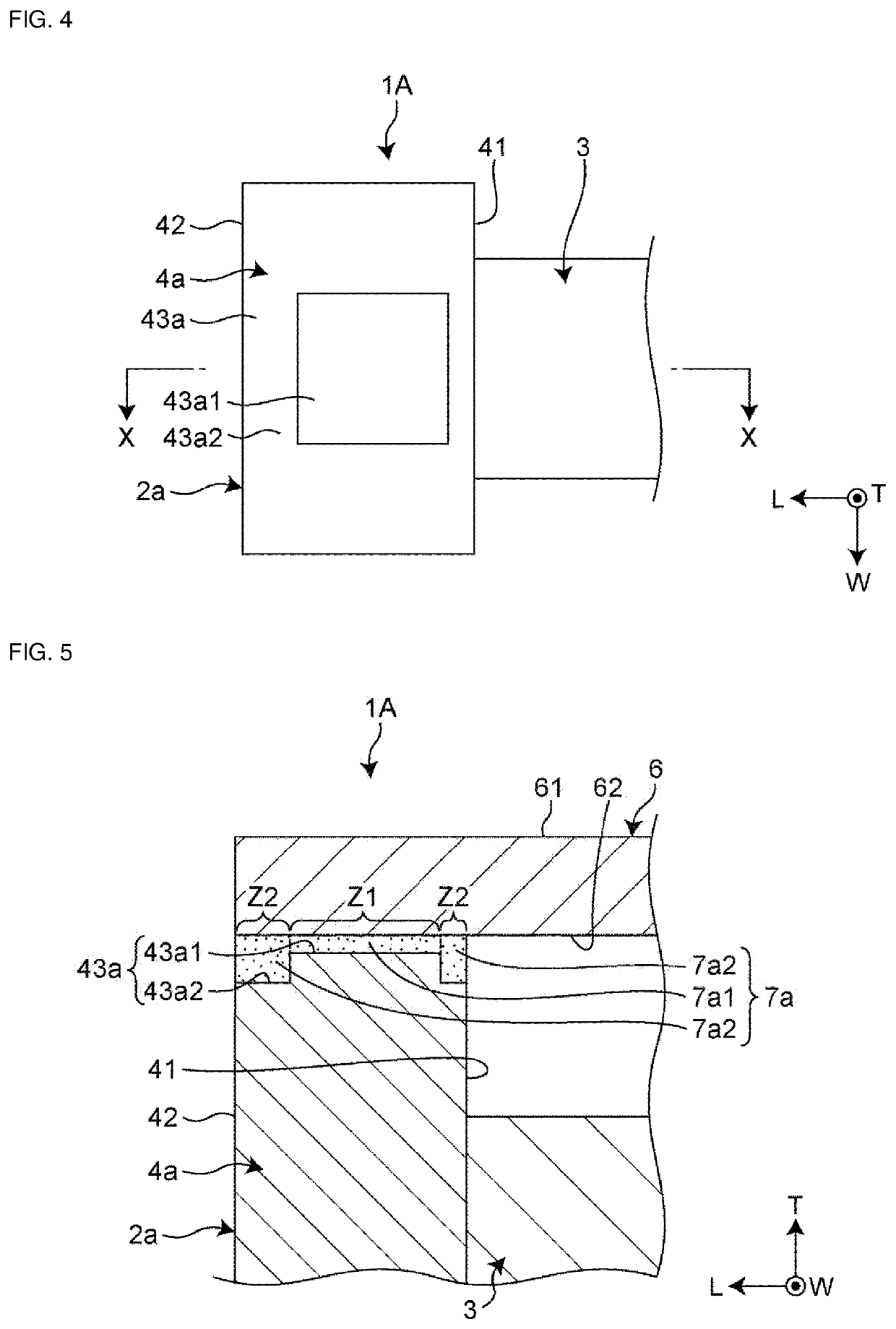
[0103]FIG. 4 is a plan view showing a coil component 1A according to a second embodiment, and is an illustration in which a first flange portion 4a of the coil component 1A is seen in the T direction. FIG. 5 is an X-X sectional view of FIG. 4, that is, a sectional view including the T direction and the L direction. Here, the plate member 6 and the wire 15 are omitted in FIG. 4, and the wire 15 is omitted in FIG. 5.

[0104]The coil component 1A is different from the coil component 1 according to the first embodiment in the shape of the upper face of a flange portion of a core. This point of difference will be described below. Other configurations are the same as those of the first embodiment, and the description may be omitted.

[0105]As shown in FIG. 4 and FIG. 5, in an upper face 43a, the first flange portion 4a of a core 2a of the coil component 1A has a flat part 43a2 and a protrusion 43a1 which is protruded toward the plate member 6 more closely than the flat part 43a2. Between the ...


PUM


Abstract

A coil component includes a core having a winding core portion, a first flange portion disposed on a first end portion of the winding core portion, and a second flange portion disposed on a second end portion of the winding core portion; a wire winding on the winding core portion of the core; and a plate member disposed so as to bridge the first flange portion and the second flange portion. The coil component further includes an adhesive portion disposed between the first flange portion and the plate member and adhering the first flange portion to the plate member, and an adhesive portion disposed between the second flange portion and the plate member and adhering the second flange portion to the plate member. The adhesive portion contains a resin and magnetic powder.

Description

CROSS-REFERENCE TO RELATED APPLICATION[0001]This application claims benefit of priority to Japanese Patent Application No. 2020-169213 filed Oct. 6, 2020, the entire content of which is incorporated herein by reference.BACKGROUNDTechnical Field[0002]The present disclosure relates to a coil component.Background Art[0003]There is a known coil component described in Japanese Unexamined Patent Application Publication No. 2015-65272. This coil component includes a core, a plate member, and a wire winding on the core, and an adhesive is disposed between the wire and the plate member to fix the core to the plate member.SUMMARY[0004]However, when an adhesive is disposed on a wire as described in Japanese Unexamined Patent Application Publication No. 2015-65272, an adhesive area cannot be reserved, thus having sometimes lowered fixation between a core and a plate member.[0005]Accordingly, the present disclosure provides a coil component that has increased fixation between a core and a plate ...

Claims


Application Information

Patent Timeline
IPC IPC(8): H01F27/28H01F27/29H01F27/255
CPCH01F27/2823H01F27/255H01F27/29H01F27/306H01F27/28H01F27/263H01F17/045H01F27/292
Inventor KONDO, KENTAHONDA, HIROYUKIMARUSAWA, HIROSHI
Owner MURATA MFG CO LTD
Why Eureka
Try Eureka