Charging station and arrangement of electric components for controlling the delivery of electricity from an electrical grid to an electric vehicle

Pending Publication Date: 2022-04-28
EASEE AS
View PDF0 Cites 1 Cited by
  • Summary
  • Abstract
  • Description
  • Claims
  • Application Information

AI Technical Summary

Benefits of technology

[0015]It is an object of the invention to provide an arrangement for a charging unit for an electric vehicle, which allows charging of the electric vehicle for all types of electric grid, earthing systems, electric signals and

Problems solved by technology

Particularly, when more than one electrical phase is available to the charging stations in a group, an inefficient situation can happen due to phase balancing issues.
For example, an inefficient situation can be observed when, in a group of charging stations protected by an electrical safety device for interrupting a three-phase power supply of the group at 32 A in any of the phases, two charging stations are each consuming 16 A from the same electrical phase.
A phase selection feature that is known to operate correctly with one combination of input electrical signals may not be suitable for another combination.
This difference can result in the wrong phase being transmitted to the electric vehicle, which in turn can result in safety risks, cause damage, or create phase balancing problems.
It can be challenging to provide a charging station for electric vehicles that allows phase selection, without knowing in advance which combination of input electrical signals will be available to the charging station.
Thus, before travelling to the site, the electrician doesn't know which input signals will be available, and thus doesn't know which type of charging station to purchase or take to the site.
Typically, the owner doesn't have sufficient technical expertise to find out or understand which combination of input signals is available in the electrical installation.
In an even worst context, the owner can buy the wrong charging station and cause damage to an electric vehicle.
Yet another example of this challenge is observed when a manufacturer of charging stations has to decide which type of charging stations with a phase selection feature is to be manufactured.
In this context, it can be difficult

Method used


Image

  • Charging station and arrangement of electric components for controlling the delivery of electricity from an electrical grid to an electric vehicle
  • Charging station and arrangement of electric components for controlling the delivery of electricity from an electrical grid to an electric vehicle
  • Charging station and arrangement of electric components for controlling the delivery of electricity from an electrical grid to an electric vehicle

Examples


Example

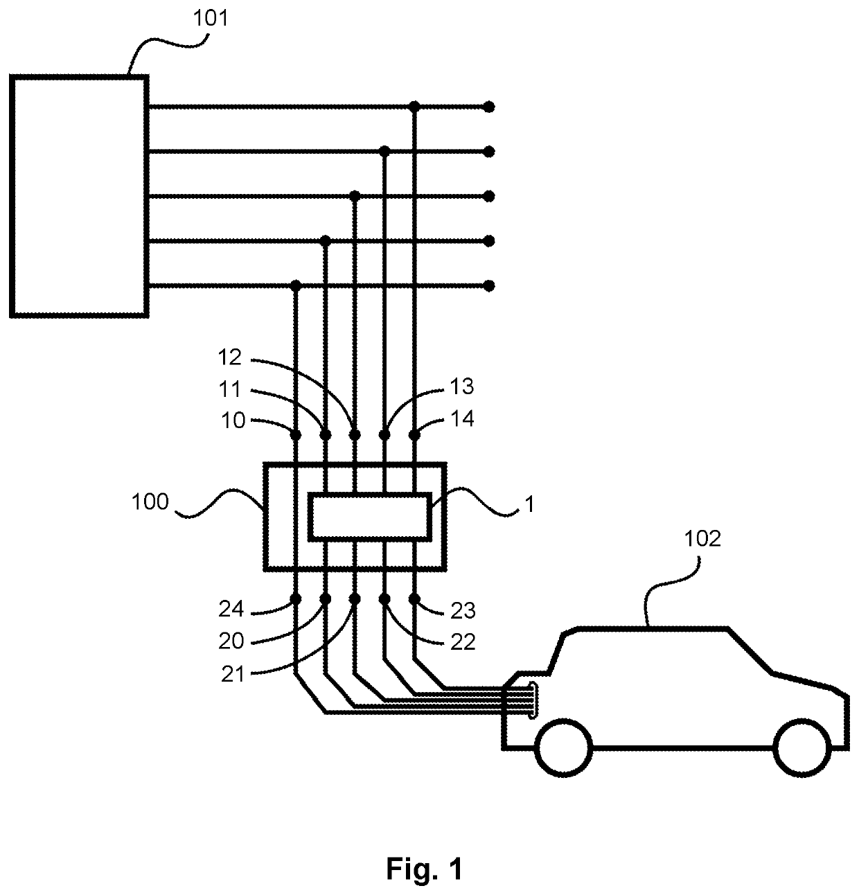
[0070]Turning now to FIG. 1, it shows an electric vehicle 102 being recharged.

[0071]The electric vehicle 102 (shown on the lower right corner of FIG. 1) is supplied with electrical power from a charging station 100 including five output terminals: a ground / protective earth output terminal 24; a neutral output terminal 20; a first-phase output terminal 21; a second-phase output terminal 22; and a third-phase output terminal 23. In practice, the connection between the electric vehicle 102 and the charging station 100 is typically implemented using a multi-conductor cable including a standard connector on each end, such as the Type 1 / SAE J1772 or the Type 2 connectors established in the international standards IEC 62196. Moreover, conductors for transmitting signalling data may also be provided in the connection between the electric vehicle 102 and the charging station 100. These signalling conductors can be used by the charging station 100 to indicate to the electric vehicle 102 which...


PUM


Abstract

Electric components for controlling the delivery of electricity from an electrical grid to an electric vehicle, the arrangement having a first, a second, a third, and a fourth input terminals, each for receiving an electric signal from the electrical grid. The arrangement also includes two switching components for controlling two connections between a neutral output terminal connectable to the electric vehicle and the first and the second input terminals. Moreover, the arrangement includes three switching components for controlling three connections between a first-phase output terminal connectable to the electric vehicle and the second, the third, and the fourth input terminals.

Description

CROSS-REFERENCE TO RELATED APPLICATIONS[0001]This application is the U.S. national stage application of International Application PCT / NO2020 / 050028, filed Feb. 5, 2020, which international application was published on Aug. 20, 2020, as International Publication WO 2020 / 167132 in the English language. The International Application claims priority of Norwegian Patent Application No. 20190184, filed Feb. 11, 2019. The international application and Norwegian application are both incorporated herein by reference, in entirety.FIELD OF THE INVENTION[0002]The present invention relates to an arrangement of electric components for controlling the delivery of electricity from an electrical grid to an electric vehicle, and it also relates to a charging station including such an arrangement.BACKGROUND OF THE INVENTION[0003]An electrical installation for recharging electric vehicles is typically organised in a tree structure in which a combination of electric signals (e.g. ground, protective eart...

Claims


Application Information

Patent Timeline
IPC IPC(8): H02J3/26H02J7/00B60L53/63B60L53/14B60L3/00
CPCH02J3/26H02J7/0013H02J2310/48B60L53/14B60L3/0046B60L53/63Y02E60/00B60L53/67B60L3/0069B60L3/04B60L2240/549H02J3/322Y02T10/70Y02T10/7072Y02T90/12B60L53/31B60Y2200/91Y04S10/126
Inventor NÆSJE, KJETILHELMIKSTØL, JONASMØLGAARD, STEFFENSTENGEL, OLA
Owner EASEE AS
Why Eureka
Try Eureka