Single screw compressor

a compressor and single screw technology, applied in the direction of machines/engines, rotary piston pumps, liquid fuel engines, etc., can solve the problems of unwanted reduction in compressor efficiency, and achieve the effect of improving the base efficiency

Pending Publication Date: 2022-05-05
J & E HALL +1
View PDF4 Cites 0 Cited by
  • Summary
  • Abstract
  • Description
  • Claims
  • Application Information

AI Technical Summary

Benefits of technology

[0007]It is an aim of the invention to eliminate this leakage path from discharge to suction and thereby to improve the base efficiency.

Problems solved by technology

The conventional VVR slide has the disadvantage that it must extend from the discharge port to the end of the rotor such that even when the slide is at the highest VR position (travel towards the discharge end of the rotor) the suction end of the rotor is sealed and no bypassing to suction can occur.
This leakage occurs when the slide is at any position and results in an unwanted reduction in compressor efficiency. FIG. 3 schematically shows the slide in place in the compressor and FIG. 4 shows the slide leakage paths 1.

Method used


Image

  • Single screw compressor
  • Single screw compressor
  • Single screw compressor

Examples


Embodiment Construction

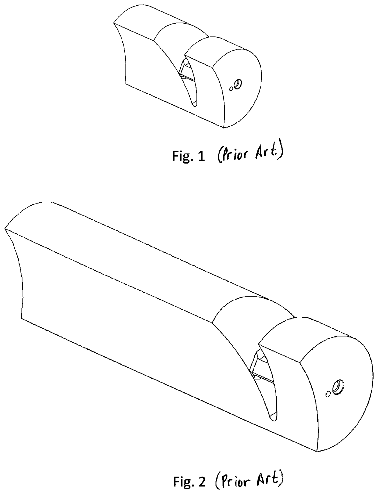
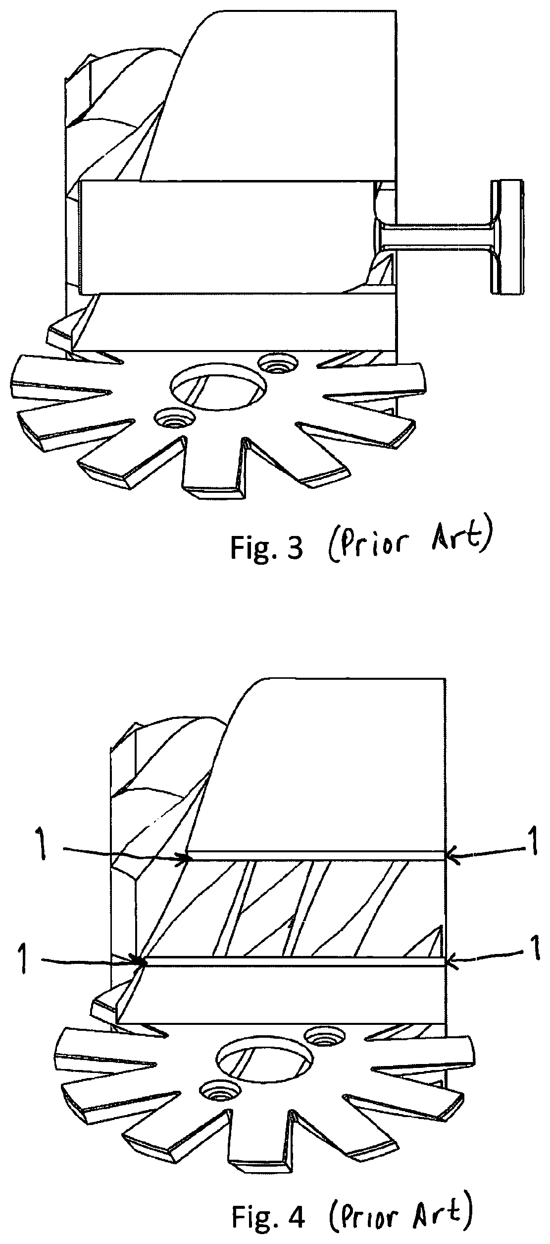
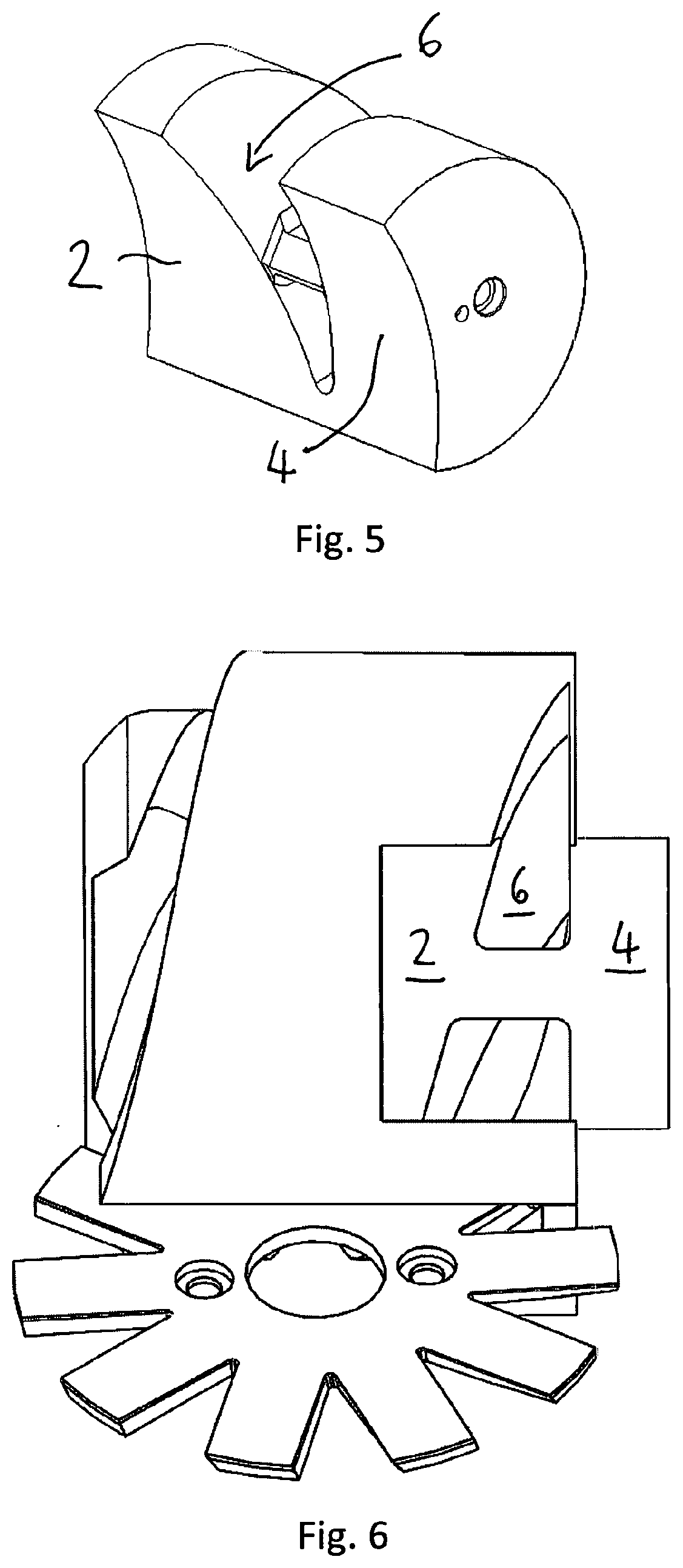
[0020]FIG. 5 shows a slide according to the invention having sealing parts 2, 4 and a cut-out 6.

[0021]FIG. 6 shows the slide of FIG. 5 positioned in towards the main casing alongside the main rotor. The cut-out 6 provides an accurate high VR discharge port.

[0022]FIG. 7 shows how a lower VR is achieved. The slide is pulled out from the casing so that it is beyond the main rotor and thus the VR is formed from the port 8 remaining in the casing.

[0023]The slide of FIGS. 5 to 7 is a simple slide. The higher VR slide discharge port provided by the cut-out 6 correctly aligns with the rotor flute, but when the slide is withdrawn beyond the rotor the remaining low VR fixed port does not match the true VR requirement.

[0024]FIGS. 8 to 10 show an alternative slide which has the same high VR cut-out as the slide of FIGS. 5 to 7. However this slide also has the correct low VR remaining in the casing when the slide is moved out of engagement beyond the rotor as shown in FIG. 10.

[0025]The simple sl...


PUM


Abstract

A single screw compressor comprises a main rotor and at least one gate rotor, a casing for the main rotor having a discharge port at a discharge end of the casing, and a slide slidable within a bore in the casing adjacent the main rotor. The slide has a cut-out (6) between first (2) and second (4) sealing parts of the slide, the slide is slidable between a high volume ratio position where the cut-out (6) is within the casing and provides a path to the discharge port, and a low volume ratio position where the slide is beyond the discharge end of the casing to provide a fixed discharge path in the bore of the casing.

Description

BACKGROUND TO THE INVENTION[0001]This invention relates to a single screw compressor with a variable volume ratio (VR).[0002]Screw compressors traditionally use slides to control the capacity of the compressor and / or the volume ratio of the compression process.[0003]Capacity control slides, such as that shown in FIG. 1, conventionally operate in the axial plane along the rotor(s). The suction end of the slides delays the start of compression by opening a bypass port during the early rotation period of the main rotor, thereby effectively reducing the swept volume (capacity) of the compressor. At the same time the delivery port opening is delayed, thus maintaining approximately constant VR during most of the compression process.[0004]Variable frequency drives are now commonly used to provide capacity control of screw compressors. However the slides are retained to provide a variable volume ratio function.[0005]As operating conditions change, the required built in volume ratio needs to...

Claims


Application Information

Patent Timeline
Patent Type & Authority Applications(United States)
IPC IPC(8): F04C18/52F04C28/12F04C3/08
CPCF04C18/52F04C3/085F04C28/12
Inventor YOUNG, TERENCE WILLIAM THOMASROLL, JOHN MICHAELVAN DER POLL, MAGHMOOD
Owner J & E HALL
Why Eureka
Try Eureka