Method and device for linking optical flow across a plurality of images of an image detection device

Pending Publication Date: 2022-05-05
ROBERT BOSCH GMBH
View PDF0 Cites 0 Cited by
  • Summary
  • Abstract
  • Description
  • Claims
  • Application Information

AI Technical Summary

Benefits of technology

[0014]In the step of starting, the new flow track may be started using a starting point in the tile, i.e., the tile to be updated at that moment. This may be the case when an enabling signal indicates an enablement of the tile for starting new flow tracks. In this way, flow tracks may advantageously be preferentially started in regions that provide an added value, for example for downstream evaluation systems. According to one specific embodiment, the new flow track may likewise be started in this tile when an object signal indicates a mapping of a relevant object in an image detail of the present image associated with the tile. The tracking of relevant objects using the flow map is thus facilitated. For example, if the present tile is not enabled for a start of a new flow track, the step of starting may be skipped, or some other tile in which the new flow track may be started may be selected.
[0015]After the step of extending, a step of sorting out may follow in which either the flow track or a further flow track is sorted out from the track map. The sorting out may take place, for example, when the end point of the flow track is occupied after the extension from an end point of the fur

Problems solved by technology

A quantization error may occur when a flow track ends on a noninteger image point, so that w

Method used


Image

  • Method and device for linking optical flow across a plurality of images of an image detection device
  • Method and device for linking optical flow across a plurality of images of an image detection device
  • Method and device for linking optical flow across a plurality of images of an image detection device

Examples


Example

[0049]In the following description of advantageous exemplary embodiments of the present invention, identical or similar reference numerals are used for the elements having a similar action which are illustrated in the various figures, and a repeated description of these elements is dispensed with.

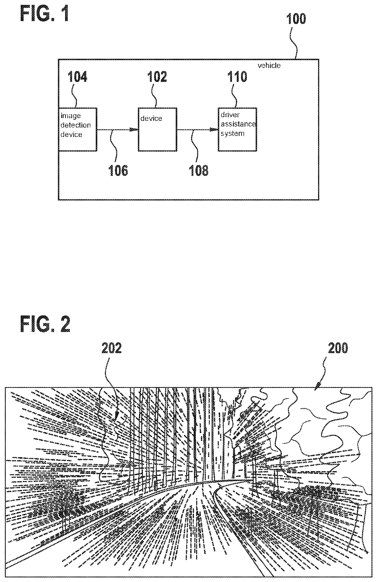
[0050]FIG. 1 shows a schematic illustration of a vehicle 100 that includes a device 102 for linking optical flow according to one exemplary embodiment. Vehicle 100 is a passenger automobile, for example. The application of the approach described here in conjunction with vehicle 100 is selected solely as an example. The described approach may also be used in conjunction with surveillance cameras, robotics, or medicine, for example.

[0051]Vehicle 100 includes an image detection device 104 which, for example, detects the surroundings of vehicle 100, in the present case an area ahead of vehicle 100 by way of example. Image detection device 104 includes one or multiple cameras, for example. For e...


PUM


Abstract

A method for linking optical flow across a plurality of images of an image detection device for a vehicle. At least one tile is selected from a track map, the track map including a plurality of flow tracks and being subdivided into a plurality of tiles. At least one flow track encompassed by the tile is subsequently extended, using a flow vector of a flow map that is associatable with the flow track. The flow map includes a plurality of flow vectors that are based on a present image of the plurality of images.

Description

CROSS REFERENCE[0001]The present application claims the benefit under 35 U.S.C. § 119 of German Patent Application No. DE 102020213587.8 filed on Oct. 29, 2020, which is expressly incorporated herein by reference in its entirety.FIELD[0002]The present invention is directed to a device or a method for linking optical flow across a plurality of images of an image detection device for a vehicle. A further subject matter of the present invention relates to a computer program.BACKGROUND INFORMATION[0003]Movements in a sequence of images may be mapped via the optical flow.[0004]German Patent Application No. DE 10 2017 214 614 A1 provides a method for the plausibility check of a flow vector hypothesis.SUMMARY[0005]Against this background, with the approach presented here a method for linking optical flow across a plurality of images of an image detection device, a device that uses this method, and a corresponding computer program are provided. Advantageous refinements and enhancements of t...

Claims


Application Information

Patent Timeline
IPC IPC(8): G06T7/215
CPCG06T7/215G06T2207/30252G06T7/246G06T7/70G06T3/4023G06T2207/20021G06T7/20G06T2207/30241G06V20/58
Inventor HERBON, CHRISTOPHER
Owner ROBERT BOSCH GMBH
Why Eureka
Try Eureka