Tracking an interventional device during an ultrasound imaging procedure

Pending Publication Date: 2022-03-10
KONINKLJIJKE PHILIPS NV
View PDF11 Cites 0 Cited by
  • Summary
  • Abstract
  • Description
  • Claims
  • Application Information

AI Technical Summary

Benefits of technology

[0027]One key advantage of the proposed mechanism is that it can be used with capacitive pressure sensing arrangements that have only two terminals/electrodes for receiving/sending signals (including power signals and ground/reference voltage signals). Thus,

Problems solved by technology

However, this approach is difficult and unreliable, as close proximity with tissue or other anatomical structure can mask the precise position of an interventional device.
However, this method exposes patient and clinicians to ionizing radiation and can require the injection of contrast fluid for improved visibility.
EM tracking uses a coil that needs to be

Method used


Image

  • Tracking an interventional device during an ultrasound imaging procedure
  • Tracking an interventional device during an ultrasound imaging procedure
  • Tracking an interventional device during an ultrasound imaging procedure

Examples


Example

[0049]The invention will be described with reference to the Figures.

[0050]It should be understood that the detailed description and specific examples, while indicating exemplary embodiments of the apparatus, systems and methods, are intended for purposes of illustration only and are not intended to limit the scope of the invention. These and other features, aspects, and advantages of the apparatus, systems and methods of the present invention will become better understood from the following description, appended claims, and accompanying drawings. It should be understood that the Figures are merely schematic and are not drawn to scale. It should also be understood that the same reference numerals are used throughout the Figures to indicate the same or similar parts.

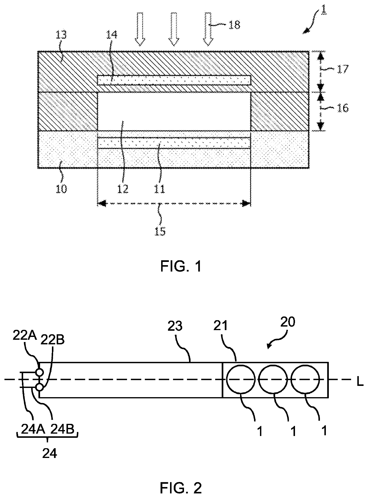
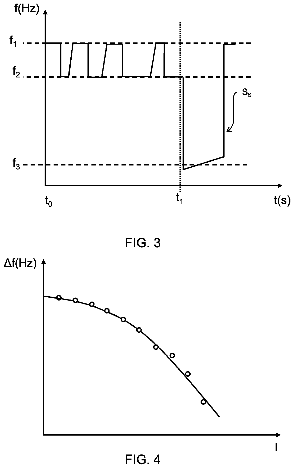
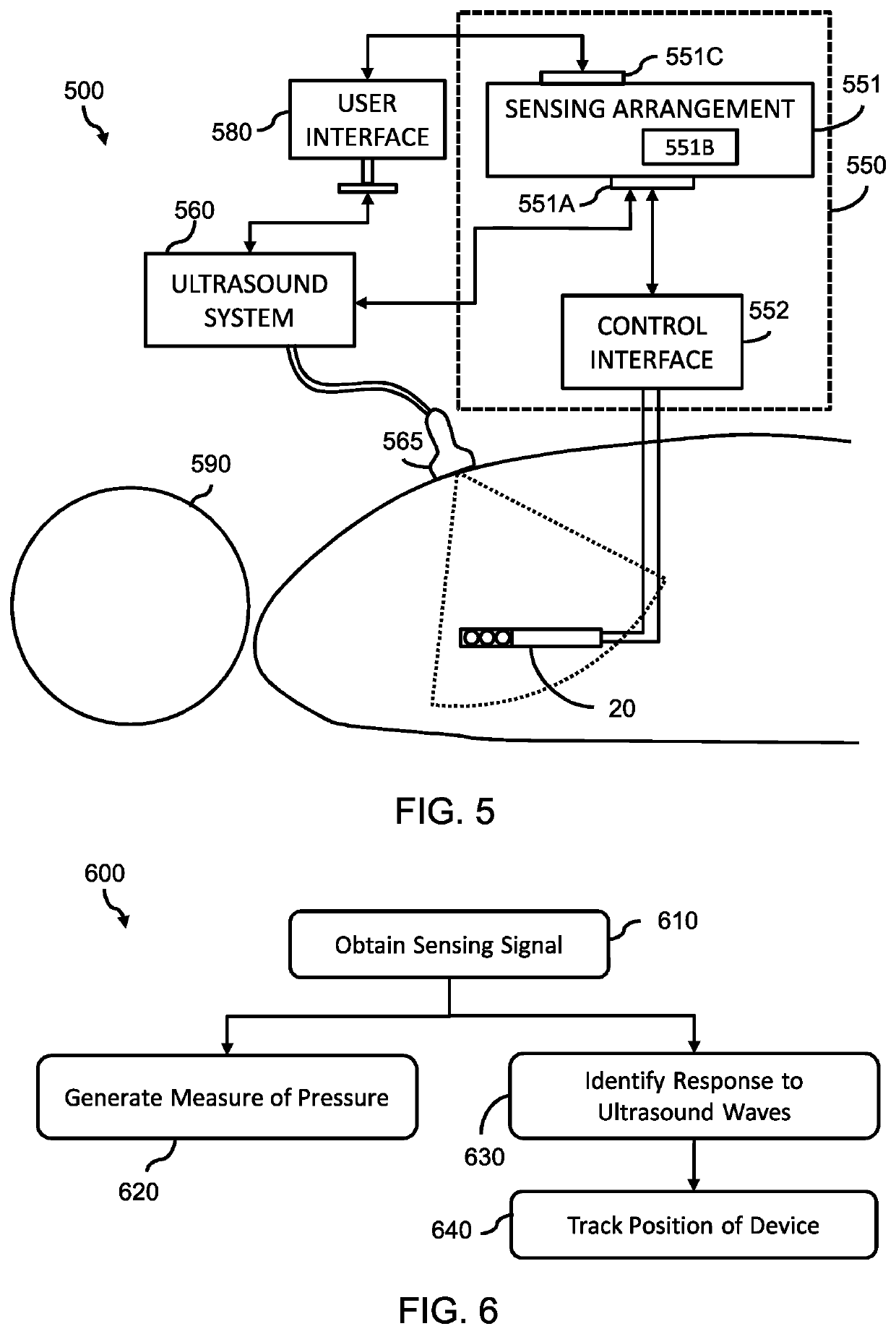
[0051]The invention provides a mechanism for tracking the position of an interventional device from a sensing signal, generated by a capacitive pressure sensing arrangement of the interventional device, responsive to a cha...


PUM


Abstract

A mechanism for tracking the position of an interventional device from a sensing signal, generated by a capacitive pressure sensing arrangement of the interventional device, responsive to a change in pressure applied to a capacitor of the capacitive pressure sensing arrangement. The sensing signal is processed to identify a first response, which is responsive to ultrasound wave(s) incident on the capacitive pressure sensing arrangement. The first response is then further processed using a tracking algorithm to track the position of the interventional device with respect to the ultrasound transducer emitting the ultrasound wave(s).

Description

FIELD OF THE INVENTION[0001]The present invention relates to the field of ultrasound imaging, and in particular, to the tracking of an interventional device during an ultrasound imaging procedure.BACKGROUND OF THE INVENTION[0002]Image-guided surgical interventions allow less invasive, less traumatic procedures. One important imaging technique used in modern surgical interventions is ultrasound. On ongoing concern is how to visualize the location and / or position of an interventional device (e.g. surgical tool, such as a catheter) within a patient.[0003]It could be possible to rely solely upon the ultrasound images generated to identify an interventional device. However, this approach is difficult and unreliable, as close proximity with tissue or other anatomical structure can mask the precise position of an interventional device.[0004]Another approach could be to use intraoperative x-ray for visualization of tools, which show up more clearly due to the difference in contrast between ...

Claims


Application Information

Patent Timeline
IPC IPC(8): A61B5/06A61B90/00A61B34/20A61B5/00
CPCA61B5/065A61B90/37A61B34/20A61B2562/0247A61B2034/2063A61B2034/2051A61B2090/3782A61B5/7228A61B2090/3786A61B2090/378A61B5/02152A61B5/6852A61B5/061A61B5/6885A61B2505/05A61B5/0215A61B8/0841
Inventor DIRKSEN, PETERTIMMERMANS, PETER HENRICUS MARIAHAARTSEN, JACOB ROGER
Owner KONINKLJIJKE PHILIPS NV
Why Eureka
Try Eureka