Floor-mounted track for installation of power outlet modules

a technology for installing power outlet modules and tracks, which is applied in the direction of electrical apparatus, connection, coupling device connection, etc., can solve the problems of not drawing elements to scale, and achieve the effects of reducing trip hazards, reducing distraction and/or negative effect on esthetics of space, and reducing trip hazards

Pending Publication Date: 2022-05-12
EMOOV LLC
View PDF4 Cites 0 Cited by
  • Summary
  • Abstract
  • Description
  • Claims
  • Application Information

AI Technical Summary

Benefits of technology

[0002]The present disclosure provides systems including tracks for installation of power outlet modules. Tracks may be installed flush with a floor to minimize distraction and / or negative effect on the esthetics of the space, reduce trip hazards, and provide convenient access to electrical power. Moreover, the locking mechanism disclosed herein to secure the power modules to the tracks or assemblies require no tools and only minimum manipulation by a user and are, thus, convenient to install, remove, or adjust. In addition, the systems disclosed herein provide safe and secure mechanical and electrical connection between the power outlet modules and the tracks while keeping the systems convenient and cost-effective.

Problems solved by technology

Furthermore, elements may not be drawn to scale.

Method used


Image

  • Floor-mounted track for installation of power outlet modules
  • Floor-mounted track for installation of power outlet modules
  • Floor-mounted track for installation of power outlet modules

Examples


Embodiment Construction

Floor Track System

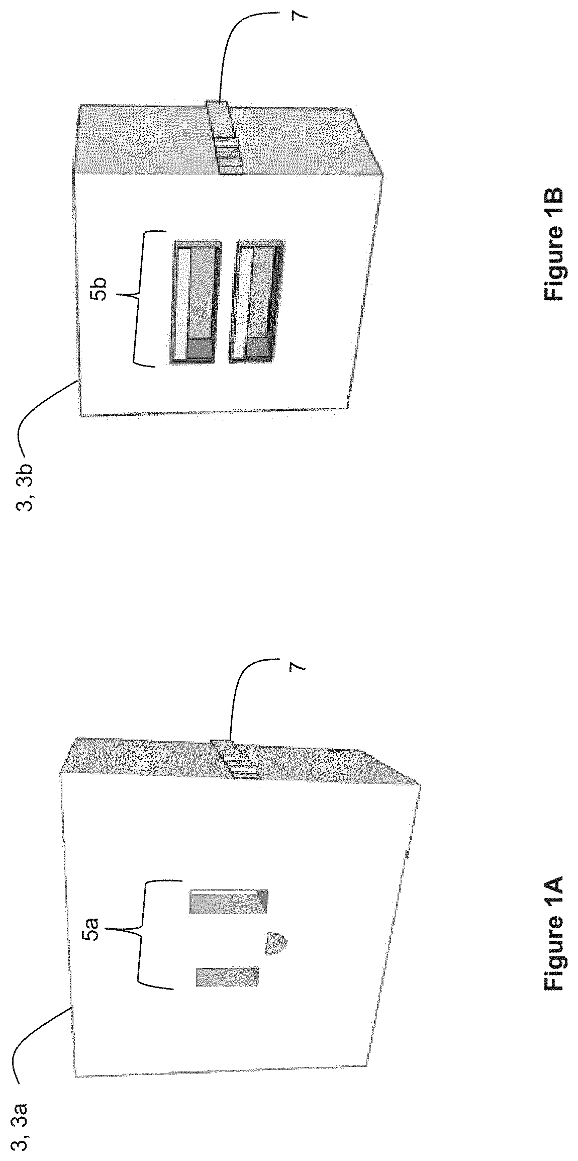
[0037]FIG. 1A through FIG. 31 illustrate perspective views of a system 1 for mechanical and electrical engagement of a power outlet module 3 to a floor F. The power outlet module 3 may be any module that provides power (AC or DC) to operate pluggable powered devices.

[0038]The power outlet module 3 may include or have built thereon one or more standard AC mains power outlet configurations (e.g., NEMA 1-15 Type A, NEMA 5-15 Type B, JIS C 8303 Class I and II, CEE 7 / 1, CEE 7 / 3, CEE 715, etc.). FIG. 1A illustrates a first type of power outlet module 3a having a receptacle 5a as a power outlet 5a and FIG. 1B illustrates a second type of power outlet module 3b having two universal serial bus (USB) ports 5b as power outlets.

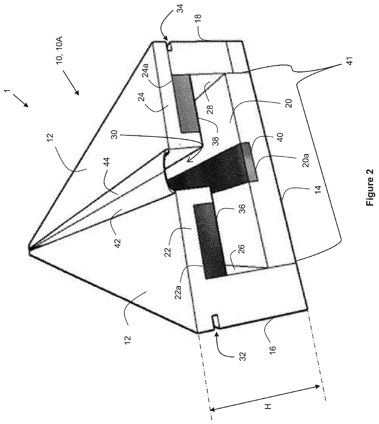
[0039]As described below, the system 1 provides convenient installation of the power outlet module 3 to the floor. To accomplish this, the system 1 may include a track 10 that may be installed flush (i.e., within), or substantially flush (i.e., substant...


PUM


Abstract

A floor-mounted track for mechanical and electrical engagement of a removable electrical power outlet module includes a bottom ran, a first rail positioned parallel the bottom rail, a first electrode engaged with the first rail and extending along at least a portion of a length of the first rail, a second rail positioned parallel the bottom rail and spaced a distance from the first rail to define a slot between a slot side of the first rail and a slot side of the second rail, a second electrode engaged with the second rail and extending along at least a portion of a length of the second rail, a first wall connecting a first side of the bottom rail to a connected side of the first rail opposite the slot side of the first rail, and a second connecting a second side of the bottom rail to a connected side of the second rail opposite the slot side of the second rail.

Description

BACKGROUND[0001]There is a need in the field for improvements to the conventional home or commercial electrical power distribution system to make it more convenient, widely available, and cost-effective.SUMMARY OF THE INVENTION[0002]The present disclosure provides systems including tracks for installation of power outlet modules. Tracks may be installed flush with a floor to minimize distraction and / or negative effect on the esthetics of the space, reduce trip hazards, and provide convenient access to electrical power. Moreover, the locking mechanism disclosed herein to secure the power modules to the tracks or assemblies require no tools and only minimum manipulation by a user and are, thus, convenient to install, remove, or adjust. In addition, the systems disclosed herein provide safe and secure mechanical and electrical connection between the power outlet modules and the tracks while keeping the systems convenient and cost-effective.[0003]The accompanying drawings, which are inc...

Claims


Application Information

Patent Timeline
Patent Type & Authority Applications(United States)
IPC IPC(8): H01R25/14H01R13/514H01R13/518
CPCH01R25/14H01R13/518H01R13/514H01R25/145H01R25/142
Inventor RAFFERTY, DEBRAVALE, FRANK
Owner EMOOV LLC
Why Eureka
Try Eureka