Projector lamp headlight with chromatic aberration correction

a technology of chromatic aberration and projector lamps, which is applied in the direction of coatings, transportation and packaging, lighting and heating apparatus, etc., can solve the problem that the metal mask can create a so-called chromatic aberration, and achieve the effect of minimizing distraction

Inactive Publication Date: 2007-02-13
REBO LIGHTING & ELECTRONICS LLC
View PDF35 Cites 20 Cited by
  • Summary
  • Abstract
  • Description
  • Claims
  • Application Information

AI Technical Summary

Benefits of technology

[0008]According to a first aspect of the invention, a reduced glare projector style headlight assembly comprises a light source for projecting visible light, a reflector adjacent the light source for directing the light in a generally forward path, an optical lens positioned in the forward path for inverting and manipulating the light into a focused beam pattern, and an opaque mask positioned in a portion of the forward path between the lens and the reflector for creating an upper shadow region in the focused beam pattern to shield on-coming traffic. The mask has a top edge which establishes a light-shadow boundary in the focused beam pattern. The mask includes a transition region proximate its top edge for passing a limited amount of projected light through the mask. By allowing traces of projected light to be introduced above the light-shadow boundary in the focused beam pattern, on-coming traffic is benefited in that all or at least some of the effects of abrupt changes in light intensity as the light-shadow boundary are reduced as the light-shadow boundary crosses into and out of view of on-coming traffic.
[0009]According to another aspect of the invention, the reduced glare projector style headlight assembly comprises a light source for projecting visible light, a reflector adjacent the light source for directing the light in a generally forward path, an optical lens positioned in the forward path for inverting and manipulating the light into a focused beam pattern, a color filter positioned in the forward path for disrupting selective wavelengths of light energy, and an opaque mask positioned in a portion of the forward path between the lens and the reflector for creating an upper shadow region in the focused beam pattern to shield on-coming traffic. The mask has a top edge establishing a light-shadow boundary in the focused beam pattern, and includes a transition region adjacent its top edge. The transition region allows a limited amount of light in the forward path to pass through the mask so that traces of projected light are introduced above the light-shadow boundary in the focused beam pattern. This, in turn, minimizes the distraction to on-coming traffic which may otherwise result from abrupt changes in light intensity as the light-shadow boundary crosses into and out of view. Any chromatic aberration created in the assembly is controlled through the color filter.
[0010]According to yet another aspect of the invention, the reduced glare projector style headlight assembly comprises a light source for projecting visible light, a reflector adjacent the light source for directing the light in a generally forward path, an optical lens positioned in the forward path for inverting and manipulating the light into a focused beam pattern, the lens containing a color filtering material for disrupting selective wavelengths of light energy in the light path, and an opaque mask positioned in a portion of the forward path between the lens and the reflector for creating an upper shadow region in the focused beam pattern to shield on-coming traffic. The mask has a top edge establishing a light-shadow boundary in the focused beam pattern, and includes a transition region adjacent its top edge. The transition region allows a limited amount of light in the forward path to pass through the mask so that traces of projected light are introduced above the light-shadow boundary in the focused beam pattern. In this configuration, on-coming traffic is not confronted with abrupt changes in light intensity as the light-shadow boundary crosses into and out of view, and any chromatic aberration created in the assembly is controlled through the color filtering lens.

Problems solved by technology

Furthermore, projector-style headlights with metallic masks can create a so-called “chromatic aberration” or undesirable chromatic effect which tends to bring different colors of light into focus at different points.
This aberration yields an effect of bright colored light bands that may annoy or confuse on-coming drivers.
Regardless of the cause, chromatic aberration is known to result in an undesirable effect in which the colored light bands often appear blue in color and are most noticeable when an on-coming vehicle having projector-style headlights hits a bump or dip in the road causing brief flashes of blue-violet light.
These flashes impose distracting glare on opposing traffic, and may confuse an on-coming driver to think the approaching vehicle is a police car or other emergency vehicle.

Method used


Image

  • Projector lamp headlight with chromatic aberration correction
  • Projector lamp headlight with chromatic aberration correction
  • Projector lamp headlight with chromatic aberration correction

Examples


Embodiment Construction

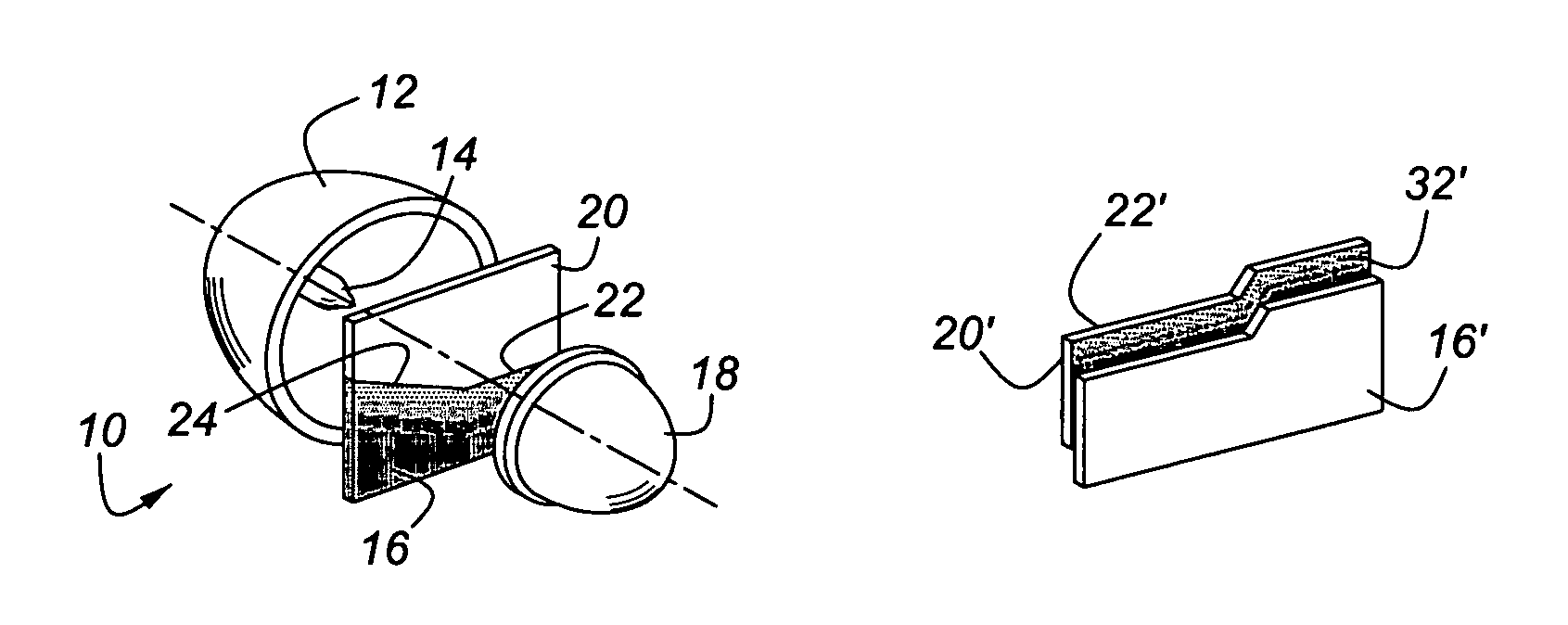
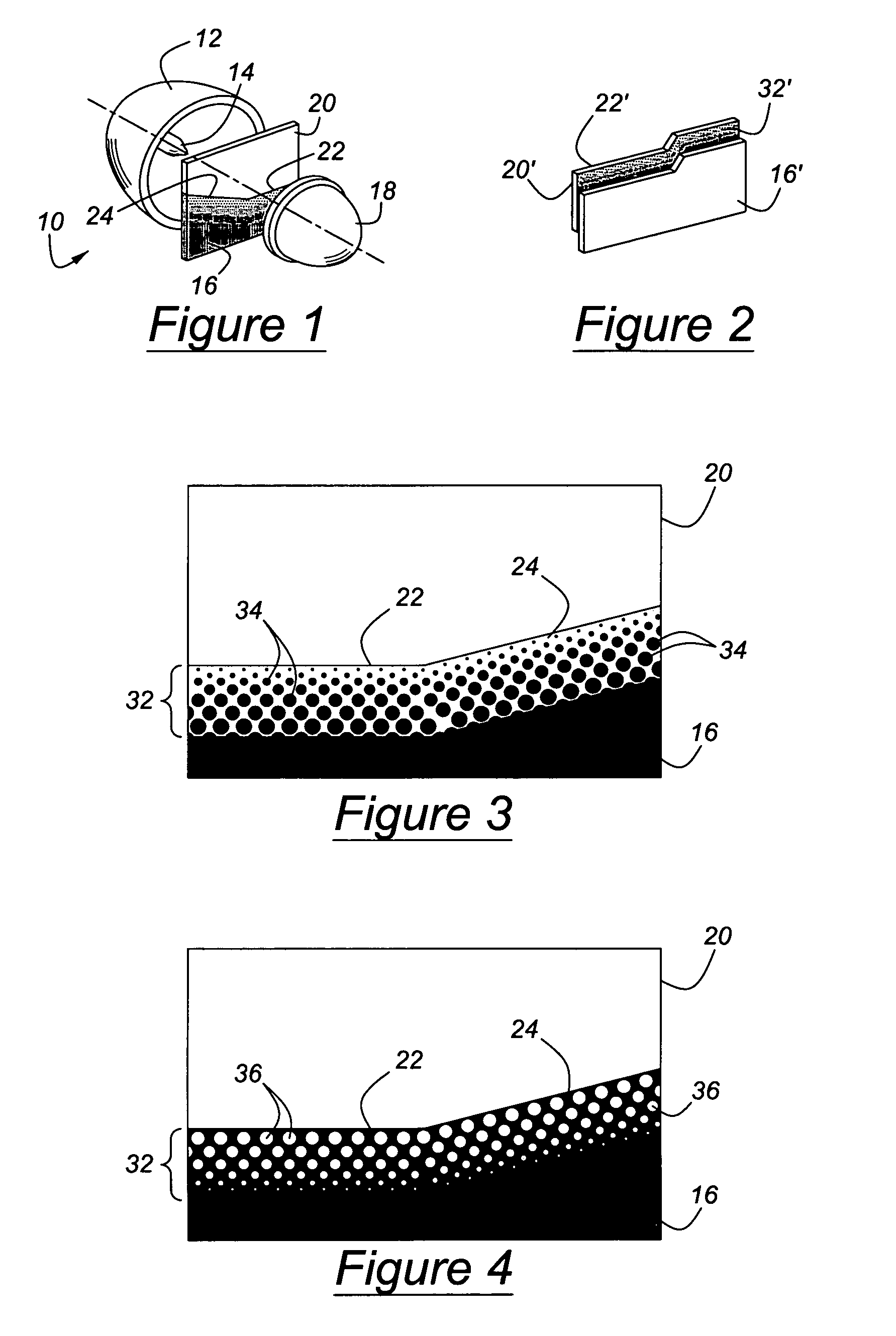
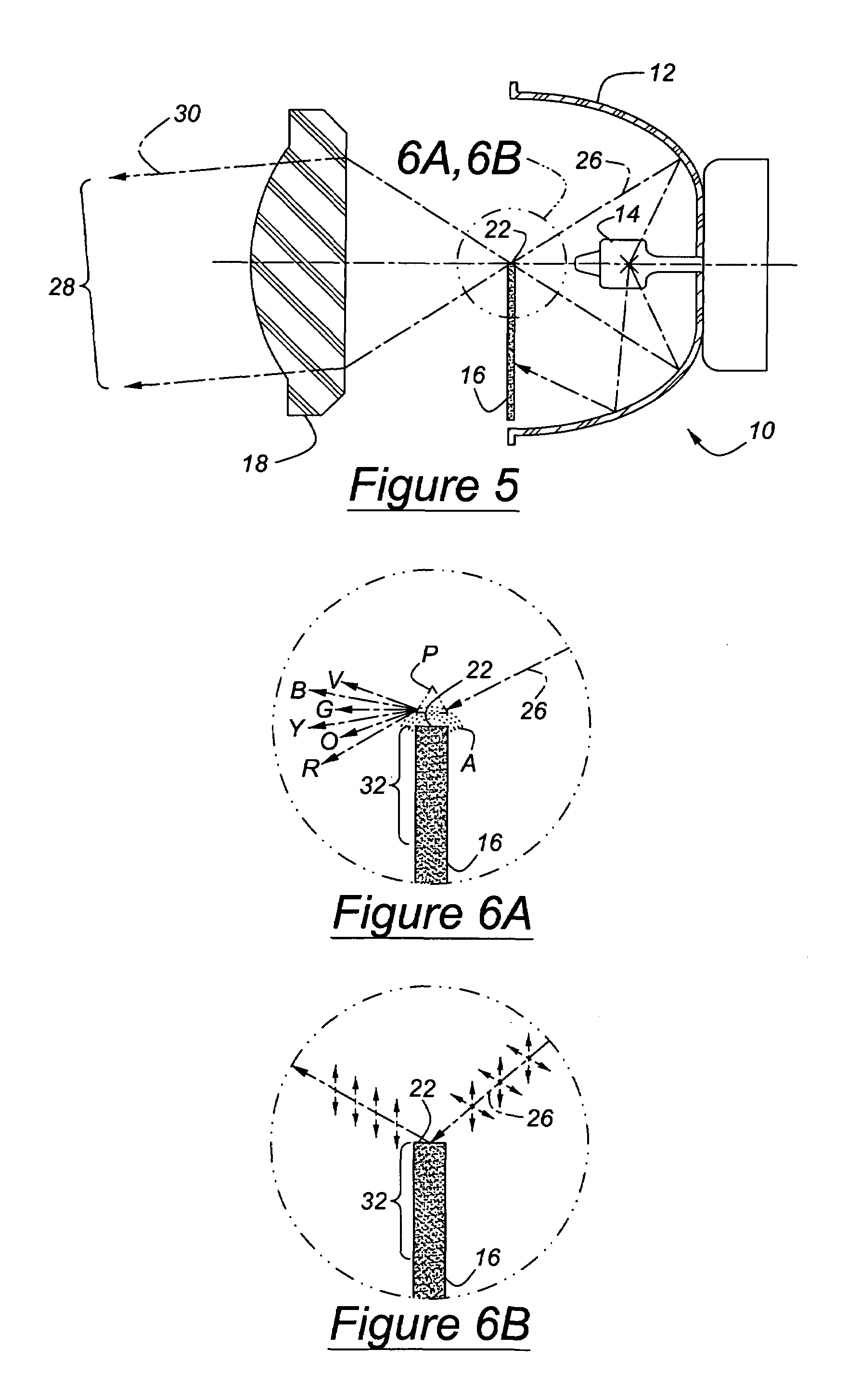
[0021]Referring to FIG. 1, there is generally shown a projection-style headlight assembly 10 that includes a reflector 12 for directing light in a generally forward path, a light source 14 positioned within the focal point of the reflector 12, an opaque mask 16 positioned forward of the light source 14, and a lens 18 positioned forward of the mask 16. The light source 14 can be of any known variety, including halogen, tungsten, high-intensity-discharge, or the like. The reflector 12, mask 16, and lens 18 are all preferably interconnected by a lens holder (not shown) and the entire headlight assembly 10 may be encased within a larger headlight housing (not shown), as is well known in the art. In contrast to the mask 16, the reflector 12, light source 14, and lens 18 as represented in FIG. 1 are components which are all substantially known and available to those of ordinary skill in the art.

[0022]The mask 16 is shown to be of substantially rectangular shape but could take other shapes...


PUM

PropertyMeasurementUnit
light intensityaaaaaaaaaa
transparentaaaaaaaaaa
areaaaaaaaaaaa

Abstract

A reduced glare projector style headlight assembly (10) comprises a light source (14), a reflector (12) and an optical lens (18). An opaque mask (16) is positioned between the lens (18) and the reflector (12) for creating an upper shadow region in the focused beam pattern (28) to shield on-coming traffic. The mask (16) includes a transition region (32) proximate its top edge (22) for allowing a limited amount of projected light to pass through the mask (16), into the upper shadow region in the focused beam pattern (28). In several embodiments, the mask (16) is applied or otherwise affixed to a transparent substrate (20) which also supports the transition region (32). To combat undesirable chromatic effects, a color filter (38) can be positioned in the light path (26) for disrupting selective wavelengths of light energy. As alternative approaches, the transparent substrate (20) and / or the lens (18′) can be doped with a color filtering material or composition.

Description

CROSS-REFERENCES TO RELATED APPLICATIONS[0001]This patent application claims priority to U.S. Provisional patent application Ser. No. 60 / 560,797, filed Apr. 8, 2004 and U.S. Provisional patent application Ser. No. 60 / 607,011 filed Sep. 3, 2004.FIELD OF THE INVENTION[0002]This invention generally relates to headlight assemblies and, more specifically, to projector-type headlight assemblies used for forward illumination in vehicles.BACKGROUND OF THE INVENTION[0003]Vehicle headlights are primarily used to provide frontal illumination for improved visibility during nighttime driving. During use, most vehicle headlights have at least two states of operation. One is the high beam state used while driving on roadways without the presence of preceding or on-coming traffic. Another is the low beam state used during most nighttime driving conditions so as to enable the driver to see the roadway ahead while limiting dazzling glare that would otherwise result from use of the high beam state.[00...

Claims


Application Information

Patent Timeline
Patent Type & Authority Patents(United States)
IPC IPC(8): B60Q1/00F21V11/06F21V9/04F21V9/06F21V9/08F21V11/14F21V11/16
CPCF21S48/145F21V9/06F21V9/08F21V9/04F21S48/1233F21S48/125F21V13/12F21V11/14F21V13/14F21S41/25F21S41/28F21S41/43F21W2102/16F21V7/28B60Q1/00B60Q1/04B60Q1/06
Inventor BUCHER, LLOYD KEITH
Owner REBO LIGHTING & ELECTRONICS LLC
Why Eureka
Try Eureka