Rearview mirror assembly with utility functions

a rearview mirror and utility function technology, applied in the field of rearview mirror assemblies, can solve the problems of obstructing the view through the windshield, hammering or obstructing the view, affecting the driver, etc., and achieve the effect of quick and easy access

Inactive Publication Date: 2006-01-05
DONNELLY CORP
View PDF99 Cites 19 Cited by
  • Summary
  • Abstract
  • Description
  • Claims
  • Application Information

AI Technical Summary

Benefits of technology

[0009] The present invention provides an interior rearview mirror assembly, which includes one or more storage spaces for storing, locating or holding objects and / or accessories all in a manner that provides quick and easy access to the objects or accessories without displacing other components or consuming valuable automaker space, such as in the dashboard of the vehicle.
[0025] In yet other aspects, the pendent accessory is pivotal from a viewing position to a stored position in the storage space. Preferably, the casing includes a recessed portion, which defines the storage space. For example, the recessed portion may be positioned at a bottom wall of the casing. Preferably, the pendent accessory includes an accessory housing, which has an outer surface that generally follows the contour of the casing when the pendent accessory is moved to the storage space to minimize the distraction to the driver.
[0028] Advantages provided by the present invention include a high mounted storage location which is easily accessible to an occupant of the vehicle and which stores a plurality of accessories, which can form a part of the interior mirror assembly or can provide a separate function or both. In addition, by incorporating the storage space into an interior rearview mirror assembly the distraction caused by retrieval from or placement into the storage space is minimized as the effort or action to retrieve or store is equivalent to the action of adjusting the position of the rearview. Further, the location of the storage space is not readily discernible from the outside of the vehicle enhancing the security of the vehicle.

Problems solved by technology

While note pad holders have been devised to attach to the windshield, by suction cups or the like, these holders often hamper or obstruct the view through the windshield and may come loose or detach.
As a result, the driver of the vehicle may have an obstructed view.
Again, when the driver engages in such activities while driving, these activities often draw the driver's eyes away from the front of the vehicle thus distracting the driver.

Method used


Image

  • Rearview mirror assembly with utility functions
  • Rearview mirror assembly with utility functions
  • Rearview mirror assembly with utility functions

Examples


first embodiment

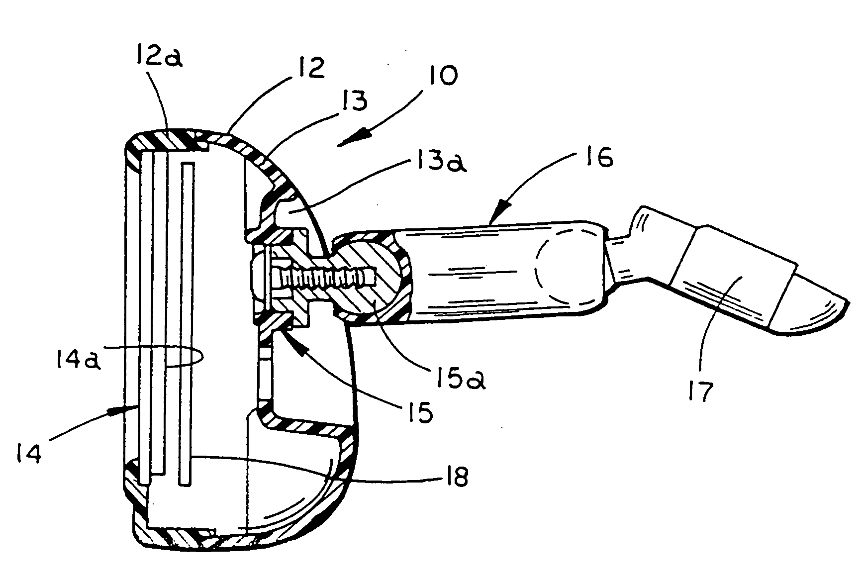
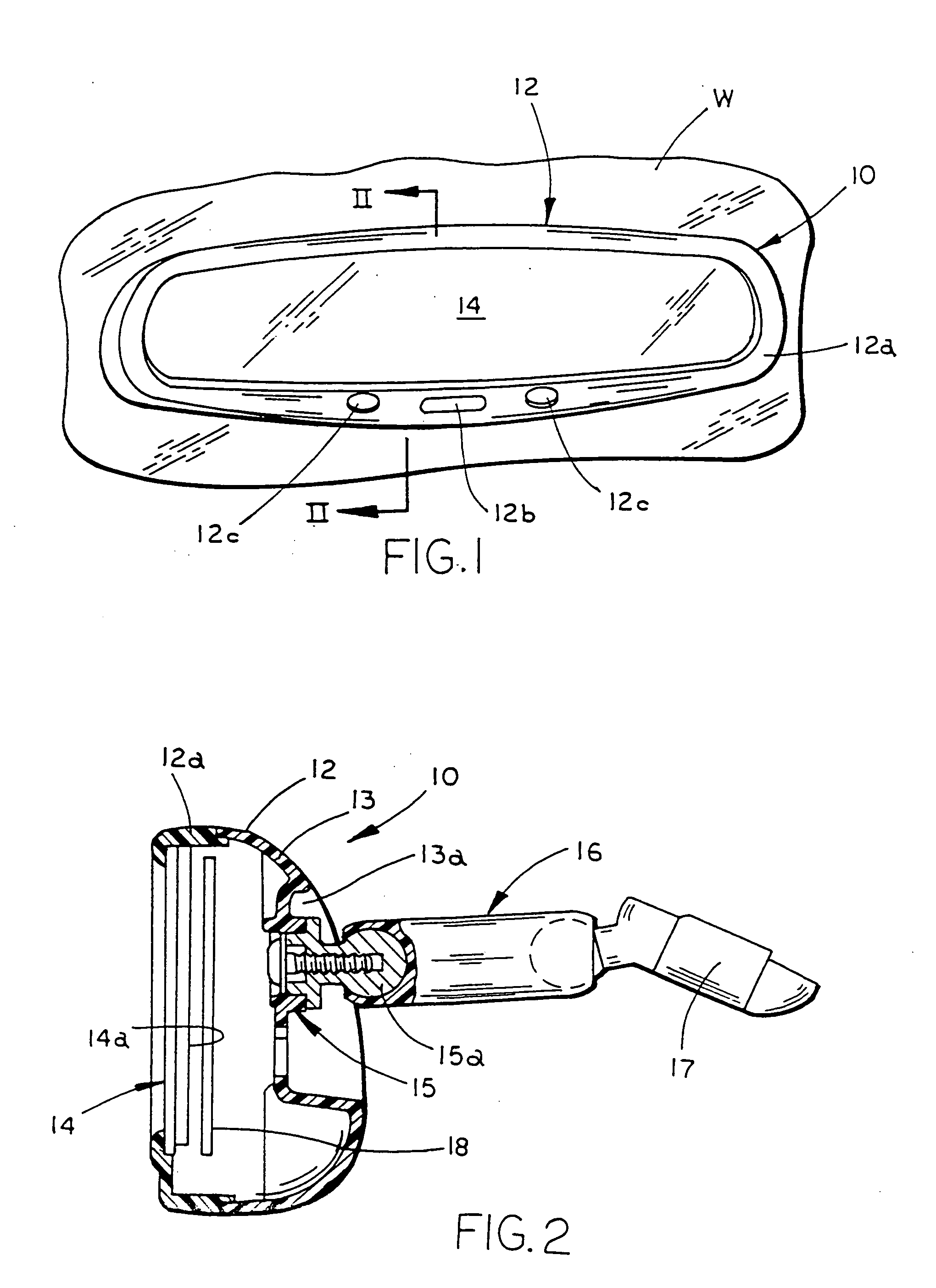
[0084] Referring to FIG. 1, the numeral 10 generally designates the interior rearview mirror assembly of the present invention. Assembly 10 is adapted to be releasably secured or coupled to the front windshield W of a vehicle in a conventional manner. Alternatively, assembly 10 can be adapted to secure or couple to the header portion of the vehicle above the windshield, as is known in the art. Assembly 10 includes a mirror casing or housing 12 and a reflective element 14 which is supported in or on casing 12 in a conventional manner. Referring to FIG. 2, in the illustrated embodiment, mirror assembly 10 is mounted to windshield W by a support arm 16 and a break-away mounting bracket or mirror mount 17 which releasably mounts to a conventional mirror button on windshield W. Preferably support arm 16 is a conventional double ball type support arm which permits multi axis positioning of casing 12 about bracket 17. It should be understood that any suitable type of support arm may be emp...

fourth embodiment

[0185] Referring to FIG. 33, the numeral 1610 generally designates the interior rearview mirror assembly illustrated in FIGS. 9-14. Mirror assembly 1610 includes a mirror housing or casing 1612, reflective element 1614, and a storage space 1622 for storing a dockable accessory 1624, similar to the previous embodiment. As previously described, dockable accessory 1624 may comprise a light assembly (shown), a telecommunications device, such as a phone or a pager or other hand held electrical or electronic devices. For further details of housing 1612, reflective element 1614 and accessory 1624, general reference is made to assembly 110.

[0186] Storage space 1622 is formed by a generally planar wall 1626 formed on back wall 1612a of casing 1612 and a generally open cavity 1628 which is formed in back wall 1612a and has a generally U-shaped configuration. Cavity 1628 is defined between planar wall 1626 and a generally U-shaped retaining wall 1628a which extends over planar wall 1626. Acces...

third embodiment

[0206] Referring to FIG. 40, a light module drive circuit 1742″ is illustrated. Circuit 1742″ comprises a capacitor powered light module circuit and includes a capacitor 1758″ and an AC / DC converter 1760″, which controls the output voltage of capacitor 1758″. Drive circuit 1742″ also includes a light source circuit 1762″ which includes an on / off switch 1764″, a load current limiter resistor 1766″ and light source(s) 1734″ which are connected in series to AC / DC converter 1760″. In addition, flashlight circuit 1742″ preferably includes a safety switch 1768″ across capacitor 1758″ to discharge the capacitor 1758″ in the event housing 1730 of light module 1715 is open. Preferably, circuit 1742″ also includes a shock protection diode 1770″ and a charge current limiter resistor 1772″. Circuit 1742″ is connected to the vehicle power supply via a second AC / DC converter 1744″ and only requires two contacts-one to ground and the other to the vehicle power supply. In this manner, when dockable...


PUM


Abstract

An interior rearview mirror assembly for a vehicle includes a housing having a mirror casing and a support for mounting said mirror casing to a vehicle. The rearview mirror assembly further includes a retractable cord for use by an occupant of the vehicle for coupling to an accessory and which is adapted to couple the accessory to a vehicle system via the housing to provide a link between the accessory and the vehicle system.

Description

[0001] This application is a divisional application of co-pending application Ser. No. 10 / 307,929, filed Dec. 2, 2002, by Barry W. Hutzel, Niall R. Lynam, Darryl P. DeWind, and John O'Lindahl, entitled AN INTERIOR REARVIEW MIRROR SYSTEM INCLUDING A PENDENT ACCESSORY, which is a divisional application Ser. No. 09 / 585,379, filed on Jun. 1, 2000, by Barry W. Hutzel, Niall R. Lynam, Darryl P. DeWind, and John O'Lindahl, entitled REARVIEW MIRROR ASSEMBLY WITH UTILITY FUNCTIONS, now abandoned, which is a continuation-in-part application of U.S. patent application Ser. No. 09 / 449,121, filed Nov. 24, 1999, now U.S. Pat. No. 6,428,172, which are herein incorporated by reference in their entireties. TECHNICAL FIELD AND BACKGROUND OF THE INVENTION [0002] The present invention relates to a rearview assembly and, more specifically, to an interior rearview mirror assembly for use in vehicles incorporating utility functions, such as storage space for holding or housing various accessories. [0003] ...

Claims


Application Information

Patent Timeline
Patent Type & Authority Applications(United States)
IPC IPC(8): B60Q3/02B60R1/12B60R11/00B60R11/02G06Q20/00
CPCB60Q3/023B60Q3/0269B60R1/008B60R1/12B60R1/1207B60R2300/8013B60R11/0241B60R11/0247B60R2001/1292B60R2011/0026B60R2011/0033B60R11/0217B60Q3/258B60Q3/59B60R1/04B60R2001/1253G01C11/02H04N7/181
Inventor HUTZEL, BARRY W.LYNAM, NIALL R.DEWIND, DARRYL P.LINDAHL, JOHN O.
Owner DONNELLY CORP
Why Eureka
Try Eureka