Improved glenoid adapter for shoulder joint prosthesis

a technology of adapters and shoulder joints, applied in the field of glenoid adapters, can solve the problems of determining the wrong cinematic of the whole reverse prosthesis, and affecting the stability of the reverse prosthesis

Active Publication Date: 2022-05-19
LIMA CORPORATE SPA
View PDF0 Cites 10 Cited by
  • Summary
  • Abstract
  • Description
  • Claims
  • Application Information

AI Technical Summary

Benefits of technology

[0029]In this way, the resurfacing prosthesis can be converted in reverse prosthesis by means of the adapter without having to remove the glenoid anchor, even if the latter is implanted in a non-central position of the glenoid cavity. The misalignment between the fixing projection and the attachment portion can be indeed advantageously chosen to position the centre of the convex articular component of the reverse prosthesis at the centre of the glenoid cavity of where it is considered more convenient in accordance with the glenohumeral morphology or with the relevant specific clinical-biomechanical needs.

Problems solved by technology

However, this implant is only for a reverse prosthesis and is not intended for a prosthesis conversion since it does not make use of an independent pivot anchor implanted in the glenoid cavity
As a person skilled in the art well knows, the removal of a previously implanted pin anchor needs the removal of a part of the surrounding bone, thus making in some cases more difficult or even impossible the stable fixing of the reverse prosthesis.
Unfortunately, in these cases, even supposing to leave the pin anchor of the resurfacing prosthesis implanted and that glenosphere adapter can be inserted in such anchor, if such pin is displaced with respect to the centre of the glenoid cavity, by using a glenosphere adapter according to the prior art, the centre of the glenosphere would not be aligned with the centre of the glenoid cavity, thus determining a wrong cinematic of the whole reverse prosthesis.

Method used


Image

  • Improved glenoid adapter for shoulder joint prosthesis
  • Improved glenoid adapter for shoulder joint prosthesis
  • Improved glenoid adapter for shoulder joint prosthesis

Examples


Embodiment Construction

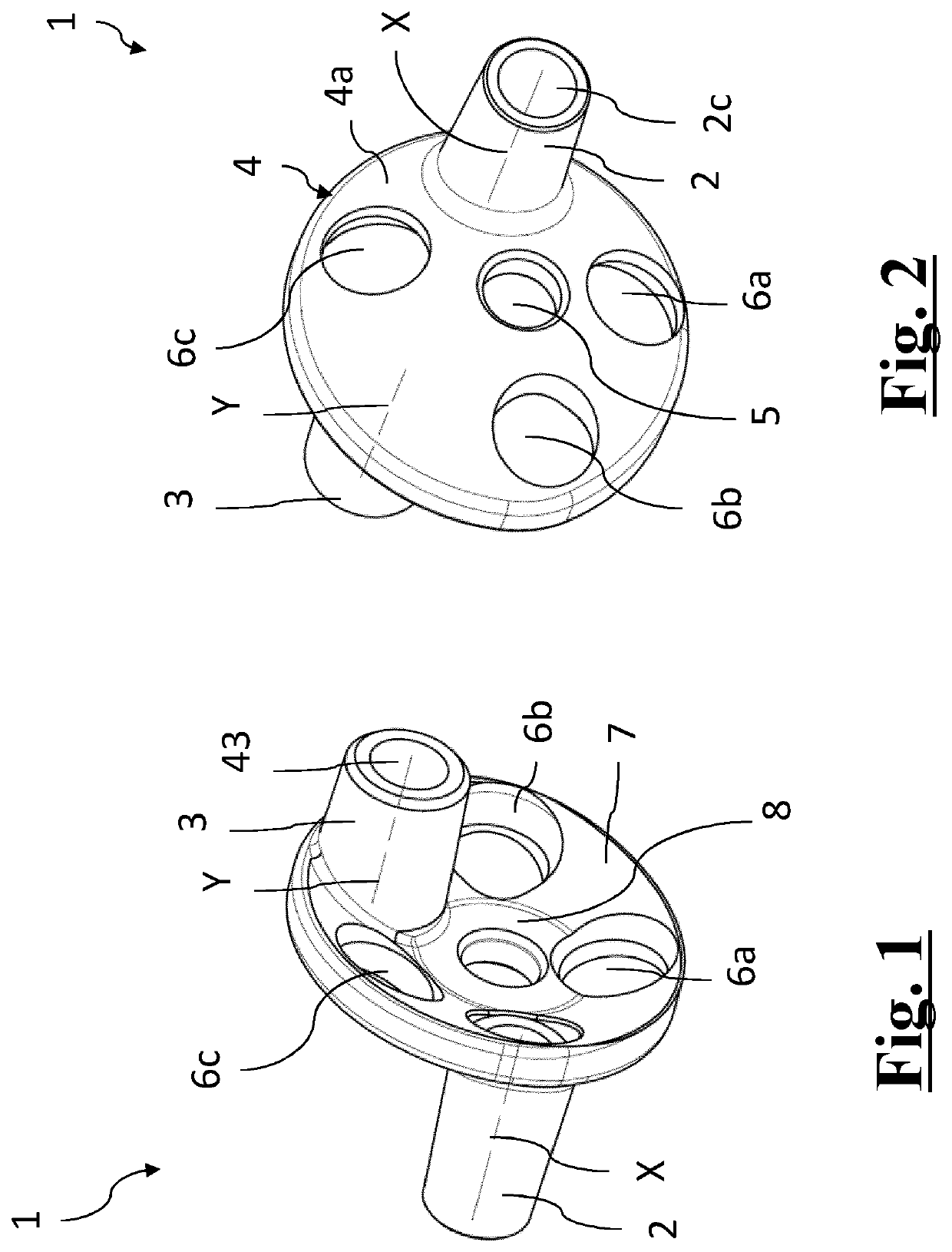
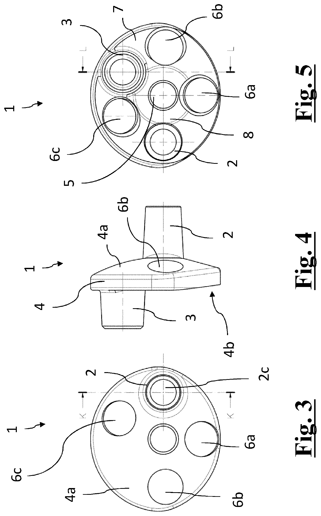
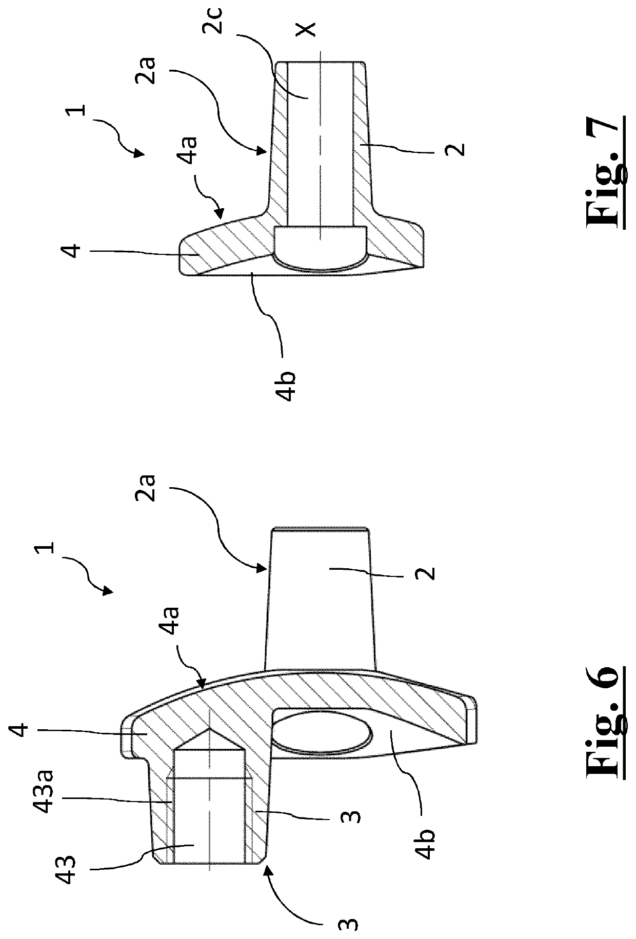
[0081]With reference to such figures, and in particular to FIGS. 1-7, a glenoid adapter 1, which is provided according to the present invention to allow a simple and correct conversion of a resurfacing shoulder prosthesis to reverse shoulder prosthesis, is globally and schematically designated with 1.

[0082]More generally, such adapter can be used for implanting a glenoid articular component of reverse prosthesis in cases where the glenoid anchor is already fixed or has to be fixed because of lack of bone tissue in a non-central area of the glenoid cavity. This does not obviously rule out the possibility to anyway use it with a central glenoid anchor to the glenoid cavity in case a displacement of the centre of the glenoid articular component with respect to centre of the glenoid cavity is needed.

[0083]In the remainder of the description, this glenoid adapter 1 will be referred to with the simpler term of adapter 1.

[0084]In the below described example of application, the adapter 1 is...


PUM


Abstract

The present invention relates to an improved glenoid adapter for shoulder prostheses, in particular for the conversion of an anatomic resurfacing prosthesis to a reverse shoulder prosthesis, comprising: •—at least one fixing projection (2) having an own axis (X) and being arranged to be fixed to the glenoid cavity (301) of the scapula (300)•—a flange (4) integral with said fixing projection (2); •—an attachment portion (3) integral with the flange (4) and extended in the direction opposite said fixing projection (2), as well as arranged to be coupled with an articular component (10) of reverse prosthesis provided with a convex articular surface (11), said attachment portion (3) having an own longitudinal axis (Y); both the fixing projection (2) and the attachment portion (3) have truncated-cone shape and that the axis of the attachment portion (Y) is misaligned with respect to the fixing projection axis (X); said flange (4) has a glenoid surface (4a) from which said fixing attachment (2) rises.

Description

FIELD OF APPLICATION[0001]The present invention relates to a glenoid adapter for implanting a convex articular component of reverse prosthesis.[0002]The invention finds particular usefulness in the conversion of a so-called anatomic resurfacing prosthesis to a reverse prosthesis, in particular in the case when the anchor of the anatomic prosthesis has been inserted in a peripheral area of the glenoid cavity; the following description is made with reference to this specific field of application in order to simplify the exposition thereof.[0003]The invention can be also employed to fix a convex component of reverse prosthesis to a glenoid cavity with lack of bone tissue on the central area, for example due to the removal of an anatomical prosthesis.PRIOR ART[0004]As it is well known, in the field of shoulder prostheses, the usage of so-called hybrid or convertible prostheses is already rather widespread which consist in modular prostheses made up of a plurality of elements which can b...

Claims


Application Information

Patent Timeline
Patent Type & Authority Applications(United States)
IPC IPC(8): A61F2/40A61F2/30
CPCA61F2/4081A61F2/30749A61F2002/30332A61F2002/4085A61F2002/30507
Inventor FATTORI, ANDREAURSELLA, SIMONE
Owner LIMA CORPORATE SPA
Why Eureka
Try Eureka