Wireless vehicle control system

Pending Publication Date: 2022-05-19
TRANSPORTATION IP HLDG LLC
View PDF0 Cites 0 Cited by
  • Summary
  • Abstract
  • Description
  • Claims
  • Application Information

AI Technical Summary

Benefits of technology

The patent describes a vehicle control system that allows a first vehicle to communicate wirelessly with another vehicle in a multi-vehicle system, while the two vehicles are not connected to each other. The system can also communicate with a third vehicle that is separate from the first and second vehicles using a cable. The wireless communication can be controlled based on information about the connection between the vehicles, and the system can use different frequency bands for transmitting vehicle control signals to the other vehicles. The technical effect of the patent is to enable efficient communication between vehicles in a multi-vehicle system without the need for cables, which can save time and reduce costs.

Problems solved by technology

Additionally, the amount of information communicated via an MU cable is significantly limited, as the cable is a twenty-seven pin cable with most of these pins carrying a binary signal and as few as a single pin carrying an analog signal.
One problem with MU control is the requirement of the MU cable to communicate signals to the locomotives that are coupled with each other.
These cables can be stolen or damaged, thereby preventing use of MU control.
Using wireless DP control for adjacent locomotives can prevent the locomotives from cohesively operating together, and can result in unsafe forces being generated between vehicles in the train.

Method used


Image

  • Wireless vehicle control system
  • Wireless vehicle control system
  • Wireless vehicle control system

Examples


Embodiment Construction

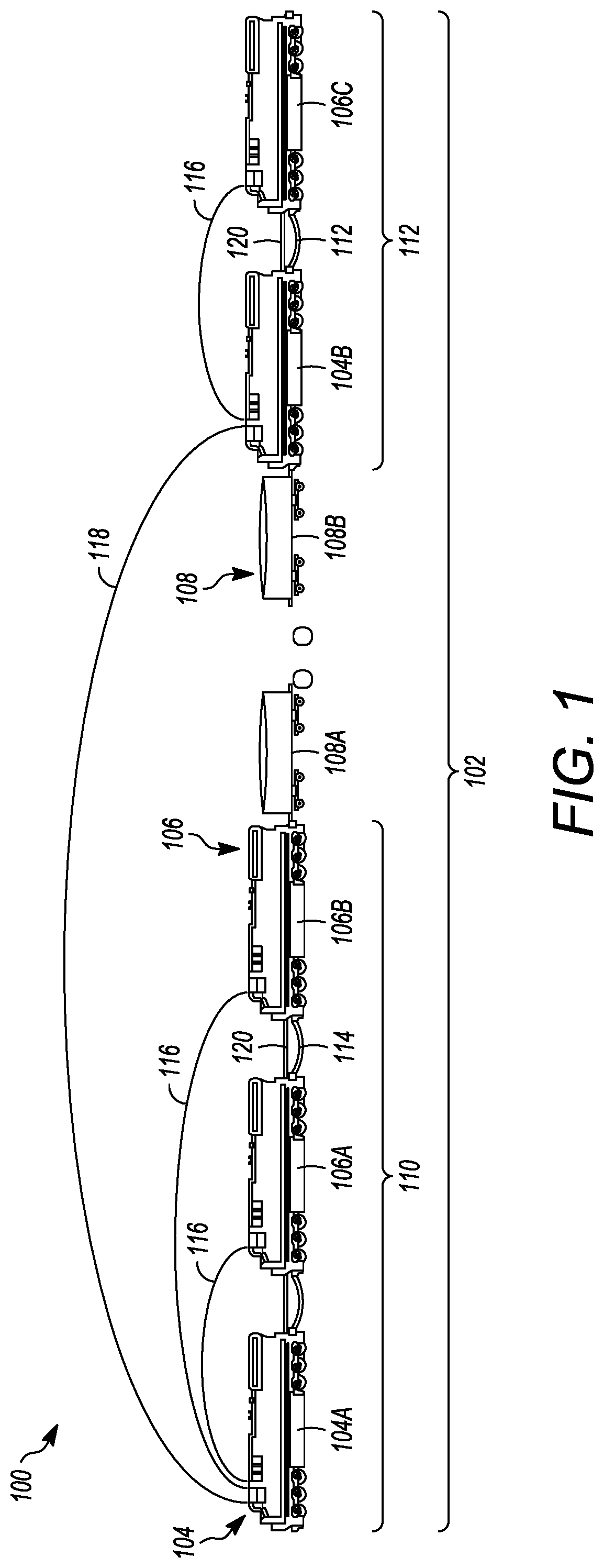
[0014]FIG. 1 illustrates one example of a vehicle control system 100 disposed onboard a multi-vehicle system 102. The vehicle system is formed from multiple propulsion-generating vehicles 104, 106 (vehicles 104A-B, 106A-C) and one or more non-propulsion-generating vehicles 108 (vehicles 108A-B). The number and / or arrangement of the vehicles 104, 106, 108 in the vehicle system may differ from what is shown in FIG. 1. In the illustrated example, the propulsion-generating vehicles are locomotives and the non-propulsion-generating vehicles are rail cars, but alternatively, these vehicles may not be rail vehicles. For example, the vehicles may be automobiles, trucks, trailers, mining vehicles, agricultural vehicles, or the like. The adjacent or neighboring vehicles in the vehicle system are mechanically coupled with each other (e.g., by couplers 118). Alternatively, two or more of the vehicles may be logically coupled but not mechanically coupled, such as where the logically coupled vehi...


PUM


Abstract

A vehicle control system includes a controller configured to be operably deployed onboard a first propulsion-generating vehicle of a multi-vehicle system, and a wireless communication unit configured to be electrically coupled to the controller. The controller is configured to control the wireless communication unit to wirelessly communicate first vehicle control signals to a second propulsion-generating vehicle of the multi-vehicle system that is immediately adjacent and mechanically coupled to the first propulsion-generating vehicle, while the first propulsion-generating vehicle and the second propulsion-generating vehicle are in a non-cable-connected state. The controller also is configured to control the wireless communication unit to wirelessly communicate different, second vehicle control signals to a third propulsion-generating vehicle of the multi-vehicle system that is separated from the first and second propulsion-generating vehicles by at least one non-propulsion-generating vehicle in the multi-vehicle system.

Description

CROSS-REFERENCE TO RELATED APPLICATIONS[0001]This application claims priority to U.S. Provisional Application No. 63 / 114,225 (filed 16 Nov. 2020), the entire disclosure of which is incorporated herein by reference.BACKGROUNDTechnical Field[0002]The inventive subject matter described herein relates to wireless control of propulsion-generating vehicles in a multi-vehicle system.Discussion of Art[0003]Some known vehicle systems can include several propulsion-generating vehicles that are coupled with each other to push and / or pull other vehicles (e.g., non-propulsion-generating vehicles). For example, some rail vehicle systems include several locomotives and rail cars or passenger cars interconnected with each other. Different control or communication schemes can be used to coordinate movements of the propulsion-generating vehicles with each other to ensure that the propulsion and / or braking generated by the different vehicles safely move the vehicle system along a route.[0004]As one ex...

Claims


Application Information

Patent Timeline
IPC IPC(8): B61L15/00B61L27/00
CPCB61L15/0027B61L2205/00B61L27/0005H04W4/46B61L27/04B61L15/0018B62D53/00B60R16/0231G08C17/02B61L15/0036B61L15/0063B61L27/70
Inventor BERNES, MAURICIOHAUSMANN, ADAMBRUTMAN, SERGIOPEREZ, VICTORRUSH, DANIELSEIP, STEVEHUTCHINS, MAURICE
Owner TRANSPORTATION IP HLDG LLC
Why Eureka
Try Eureka