
Compensating for polarization changes introduced by components with retardation in polarization-sensitive retinal scanning systems

Pending Publication Date: 2022-06-02
THE JOHN HOPKINS UNIV SCHOOL OF MEDICINE
View PDF0 Cites 0 Cited by
  • Summary
  • Abstract
  • Description
  • Claims
  • Application Information

AI Technical Summary

Benefits of technology

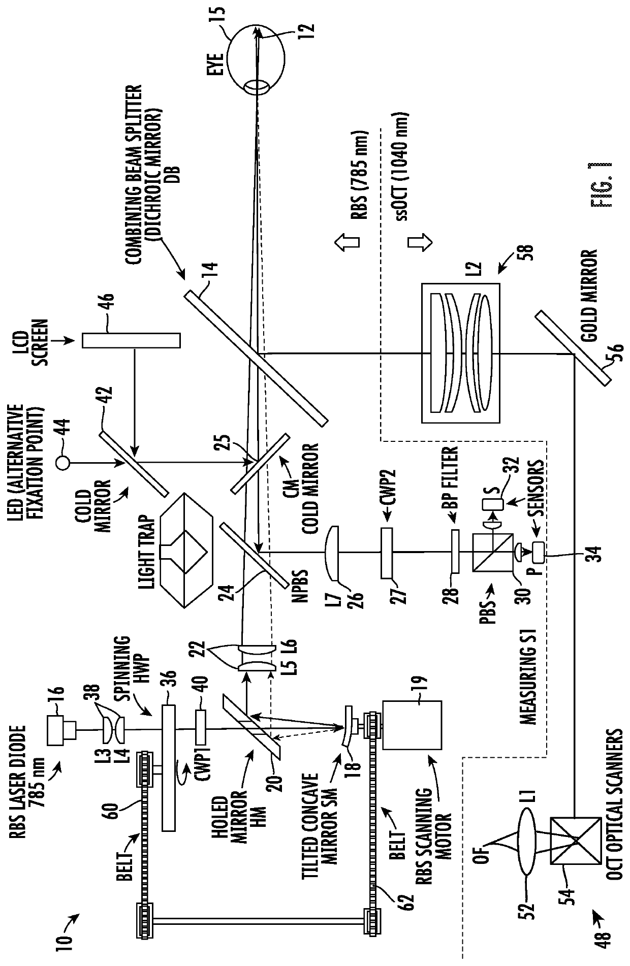
The present invention provides an optical system and method for detecting the fixation condition of an eye by analyzing the birefringence properties of the retina using polarized light. This is achieved by imaging the polarized light onto the retina and capturing the reflected light, which is then analyzed to determine the amount and orientation of the birefringence. The system is designed to account for interference with polarization measurements caused by unwanted retardance, which is a type of birefringence, by using a compensating retarder to nullify the effects of unwanted retardance. This ensures that accurate measurements can be made of the birefringence properties of the retina.

Problems solved by technology

The optical system contains unwanted retardance, wherein the unwanted retardance can cause interference with polarization measurements which alters the polarization state of the light entering the eye and of the light reaching the detection system.

Method used


Image

  • Compensating for polarization changes introduced by components with retardation in polarization-sensitive retinal scanning systems

Examples


Embodiment Construction

[0012]The presently disclosed subject matter now will be described more fully hereinafter with reference to the accompanying Drawing, in which some, but not all embodiments of the inventions are shown. Like numbers refer to like elements throughout. The presently disclosed subject matter may be embodied in many different forms and should not be construed as limited to the embodiments set forth herein; rather, these embodiments are provided so that this disclosure will satisfy applicable legal requirements. Indeed, many modifications and other embodiments of the presently disclosed subject matter set forth herein will come to mind to one skilled in the art to which the presently disclosed subject matter pertains, having the benefit of the teachings presented in the foregoing descriptions and the associated Drawing. Therefore, it is to be understood that the presently disclosed subject matter is not to be limited to the specific embodiments disclosed and that modifications and other e...


PUM


Abstract

An optical apparatus uses polarized light to interrogate birefringence properties of the retina to detect the fixation condition of the eye by sensing characteristic birefringence patterns of the retinal structures. Optical components, as well as optional additional components, interfere with the polarization measurements by introducing unwanted retardance which alters the polarization state of the light entering the eye and of the light reaching the detection system. Compensating retarders are provided to nullify the effect of unwanted retardance in the forward and return light paths so the polarization states of the light entering the eye and the light reaching the detection system are not contaminated by the effects of the unwanted retardance. Mueller matrices are used to mathematically calculate the parameters for the compensating retarders for the unwanted retardance. A variable retarder system may also be provided to compensate for the corneal birefringence of the eye via feedback control.

Description

CROSS REFERENCE TO RELATED APPLICATIONS[0001]This application claims the benefit of U.S. Provisional Patent Application No. 62 / 829,307 filed on Apr. 4, 2019, which is incorporated by reference, herein, in its entirety.FIELD OF THE INVENTION[0002]The present invention relates generally to retinal imaging. More particularly, the present invention relates to compensating for polarization changes introduced by components with retardation in polarization-sensitive retinal scanning systems.BACKGROUND OF THE INVENTION[0003]In practical designs of polarization-sensitive systems, it is important to keep track of the polarization state of light along most beam paths. This can be done by using a Polarization Tracing Model. This formalism uses a train of Mueller matrices treating each polarization-altering element in the system as a retarder, where the retardation of the light beam is changed by transmission through, or reflection from, the polarization-altering element. Oftentimes, the designe...

Claims


Application Information

Patent Timeline
IPC IPC(8): A61B3/12A61B3/10A61B3/113A61B3/14
CPCA61B3/12A61B3/14A61B3/113A61B3/102
Inventor GRAMATIKOV, BORISGUYTON, DAVID
Owner THE JOHN HOPKINS UNIV SCHOOL OF MEDICINE
Learn More