Shower pans and related linear drain configurations

Active Publication Date: 2022-06-23
TILE REDI
View PDF8 Cites 0 Cited by
  • Summary
  • Abstract
  • Description
  • Claims
  • Application Information

AI Technical Summary

Benefits of technology

[0015]Employing the teachings of this invention permits a manufacturer to minimize the number of unique product SKUs which it manufactures and or inventories, while maximizing the number of unique solutions that can be offered to customers. In some embodiments, most or all shower floor grout lines are eliminated by the use of large (i.e., monolithic) floor covering members, creating a desirable visual effect. These benefits are achievable notwithsta

Problems solved by technology

However, it is believed that consumers, for whatever reason, may be uncomfortable with the idea of standing on such apertured grates.
This phenomenon, in turn, has limited the employment of shower trenches and trench drains for so-called “center” drain locations, where the person using the shower typically would stand.
Also, objections have been raised to the inconvenience and difficulty of removing and manipulating the bulky and heavy linear drain covers to access the drain and clean the trench, particularly where the linear drain cover is tiled over, making it heavier and more difficult to handle, and where the linear drain is located around the perimeter of the shower.
There is real risk that these large grates will damage surrounding wall and/or wall tile, as well as the tile on the drain cover if it is tiled.
The net effect of these and other objections to trenches not being consumer friendly has prevented shower trenches and trench drains from achieving the same kind of consumer acceptance as other drains, and has prevented consumers from enjoying the aesthetics of shower trenches and trench drains anywhere and everywhere in their shower.
However, there has not been a suitable solution for the use of linear drains in center drain locations, and the current solutions for linear drain locations not located around the perimeter of the shower have significant drawbacks related to the handling of the drain grates for purposes of accessing the linear drains for cleaning purposes and accessing the waste water pipe, sales of linear drains, shower trenches, trench dr

Method used


Image

  • Shower pans and related linear drain configurations
  • Shower pans and related linear drain configurations
  • Shower pans and related linear drain configurations

Examples


Embodiment Construction

)

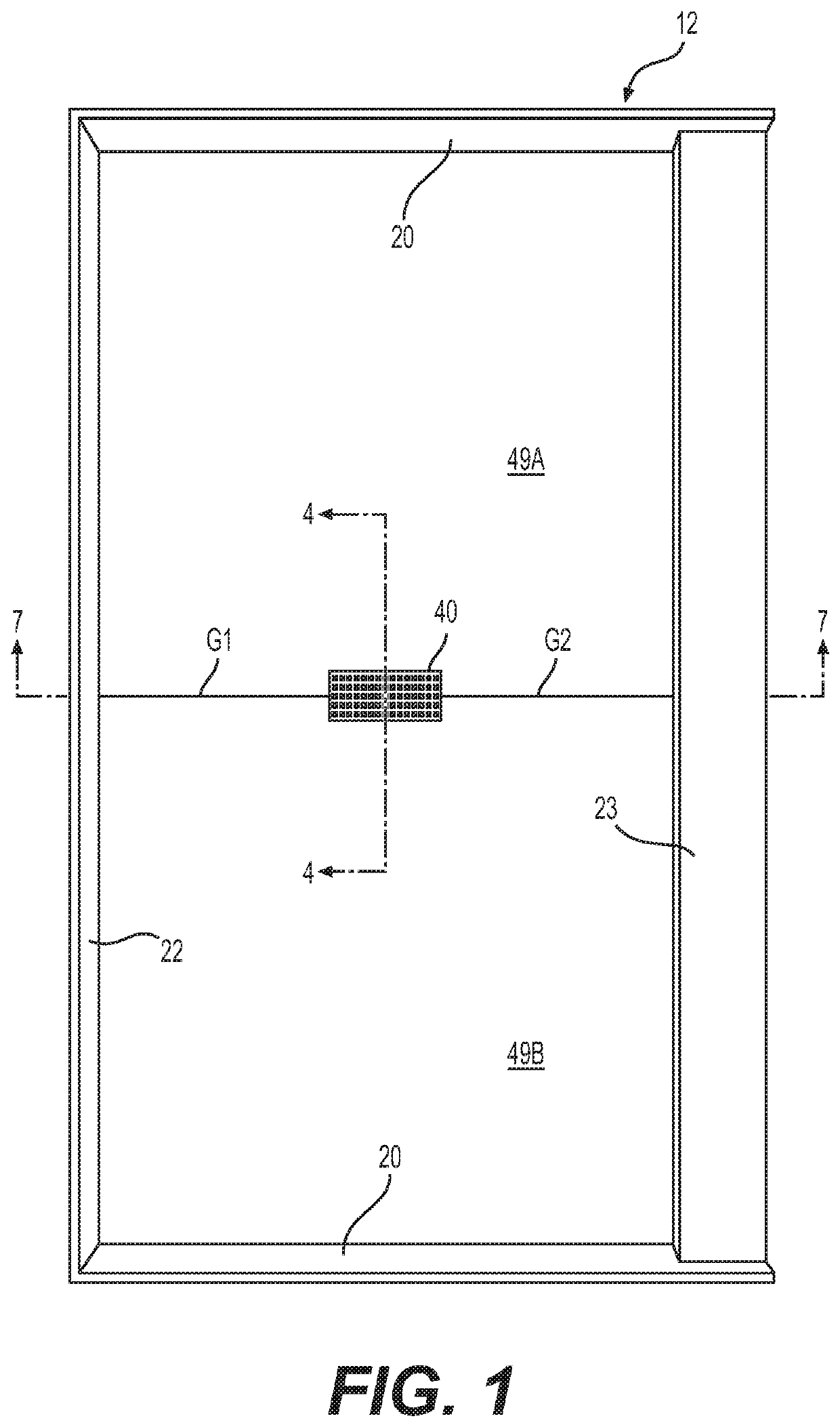
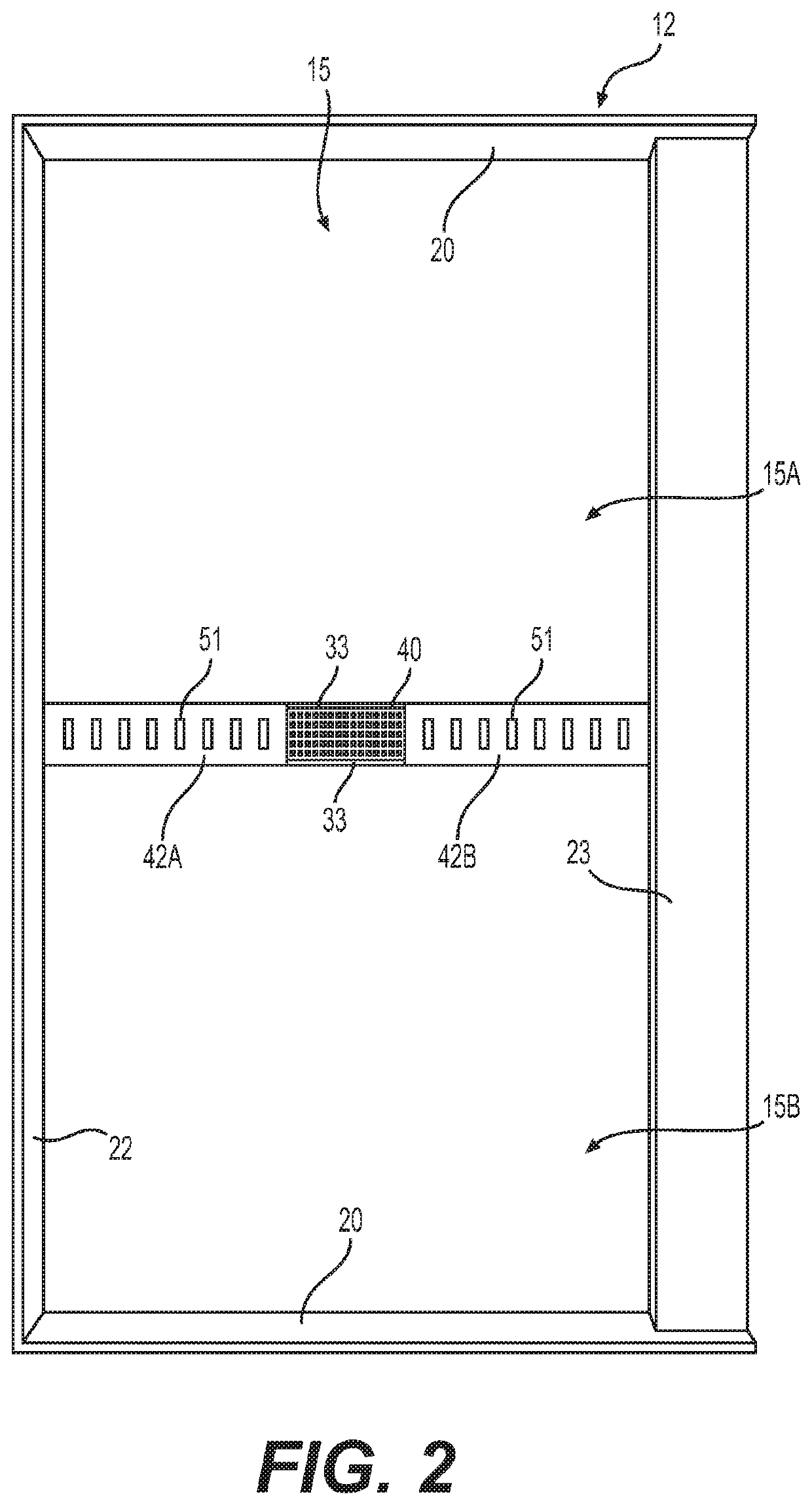
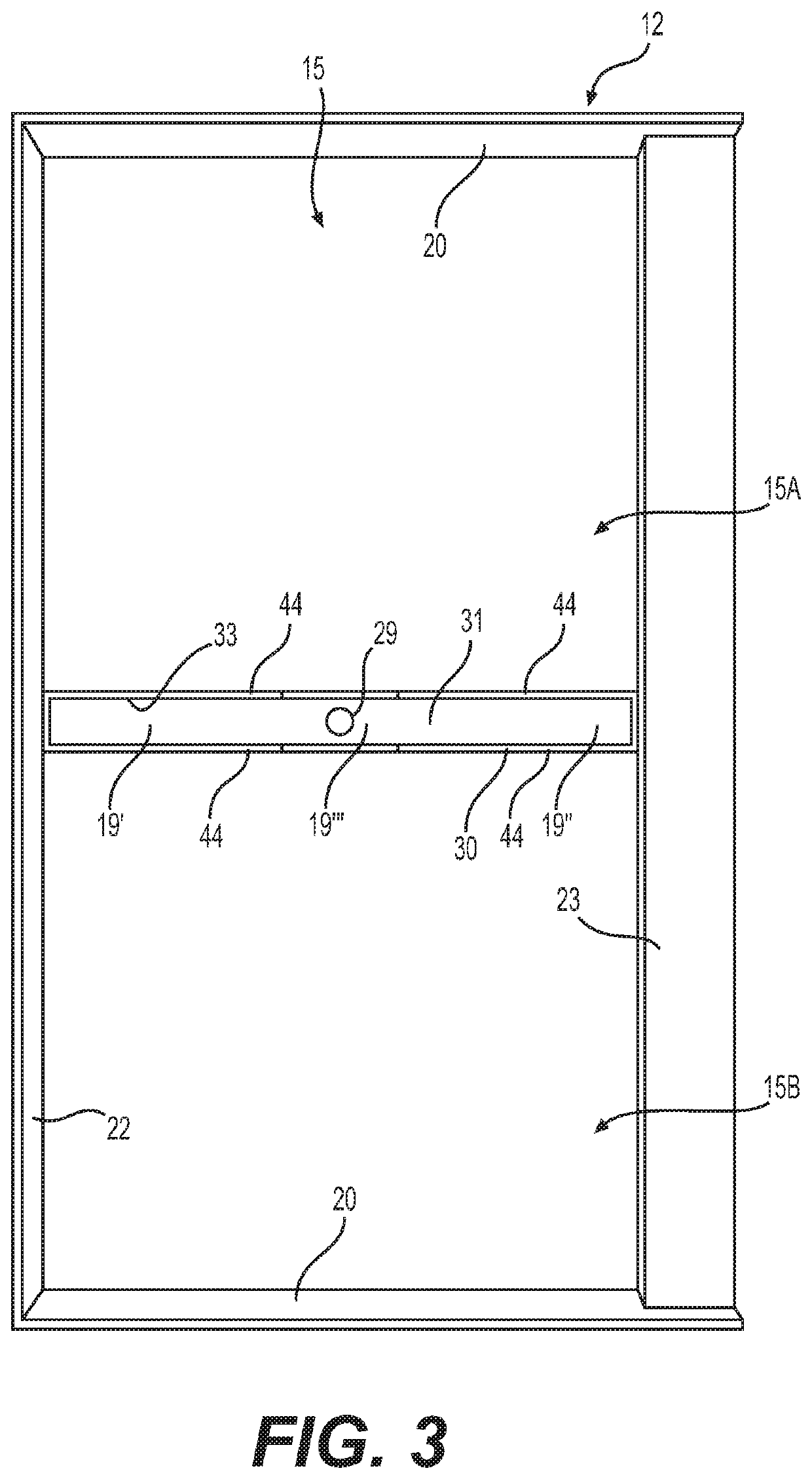
[0072]The inventive embodiments of my invention reside primarily in combinations of structural components and manufacturing, installation and use steps related to the creation of a variety of shower floors incorporated into shower pan and drain arrangements in which at least a portion of the actual drainage apparatus is concealed from visual inspection.

[0073]Accordingly, the apparatus components have been represented where appropriate by conventional symbols in the drawings, showing only those specific details that are pertinent to understanding the embodiments of the present invention so as not to obscure the disclosure with details that will be readily apparent to those of ordinary skill in the art having the benefit of the description herein.

[0074]In this document, relational terms, such as “first” and “second,”“top” and “bottom,” and the like, may be used solely to distinguish one entity or element from another entity or element without necessarily requiring or implying any phy...


PUM


Abstract

A drainable floor and linear drain, the drainable floor having an integral trench associated therewith, the trench comprising sidewall and a trench floor, and one or more floor covering panels positioned in registry with the drainable floor, where the one or more floor covering panels cover a portion of the projection of the trench floor, while leaving at least one other portion of the trench floor uncovered by such one or more floor covering panels.

Description

BACKGROUND OF THE INVENTIONField of the Invention[0001]The present invention relates generally to showers and other drainable structures, and associated trench (i.e., elongated) drains, and to shower trenches associated with any drain, and more particularly to shower pans with trench drains or shower trenches with associated drains, or both, where the dimensions of the trench may be different from the dimensions of the drainage apertures through which water drains into the trench.Description of the Prior Art[0002]Water can be drained from surfaces such as tables and floors by many different arrangements. For example, shower floors must have drains, i.e., apertures, positioned therein to permit water to drain into the wastewater drain in the subfloor. Linear, or elongated, drains have become popular for use in showers and elsewhere. Such drains are typically covered by apertured grates which conceal the interior of the trench and wastewater drain but which define slots, holes or othe...

Claims


Application Information

Patent Timeline
IPC IPC(8): A47K3/40
CPCA47K3/40E03F5/0408
Inventor COOK, JOSEPH R.
Owner TILE REDI
Why Eureka
Try Eureka