Method and device for influencing an optical output of image data on an output device in a vehicle

a technology of image data and output device, which is applied in the direction of static indicating device, instruments, transportation and packaging, etc., can solve the problems of no longer being able to see any image data on the output device, and reducing the blurring of the output image data. , the effect of increasing the blurring of the output image data

Active Publication Date: 2022-06-23
DAIMLER AG
View PDF10 Cites 0 Cited by
  • Summary
  • Abstract
  • Description
  • Claims
  • Application Information

AI Technical Summary

Benefits of technology

[0051]Advantageously, the control unit is designed and set up in such a way that the fading out of the optical output of the image data is implemented with a step function TFADING OUT(t), in which the light intensity LI of the image data output is reduced stepwise, and / or in which the blurring of the image data output is increased stepwise.
[0052]Advantageously, the control unit is designed and set up in such a way that the fading in of the optical output of the image data is implemented with a step function TFADING IN(t), in which the light intensity LI of the image data output is increased stepwise, and / or in which the blurring of the image data output is reduced stepwise.

Problems solved by technology

The reproduction of image data, in particular moving images, such as: videos, animations, clips etc. on optical output devices that can be viewed by the driver of the vehicle, is not permitted in numerous countries for safety reasons during operation of the vehicle due to the high distraction potential for the respective driver.
The process of fading out preferably takes place over a predetermined period of time >0 and, once it has proceeded undisturbed, results in a person no longer being able to see any image data on the output device.
If a passenger is present at all, he / she will, if he / she is interested in viewing the optically output image data, additionally exert a certain psychological pressure on the driver, which causes the driver not to look at the output device, such that an undisturbed viewing of the output image data by the passenger is possible.

Method used


Image

  • Method and device for influencing an optical output of image data on an output device in a vehicle
  • Method and device for influencing an optical output of image data on an output device in a vehicle

Examples


Embodiment Construction

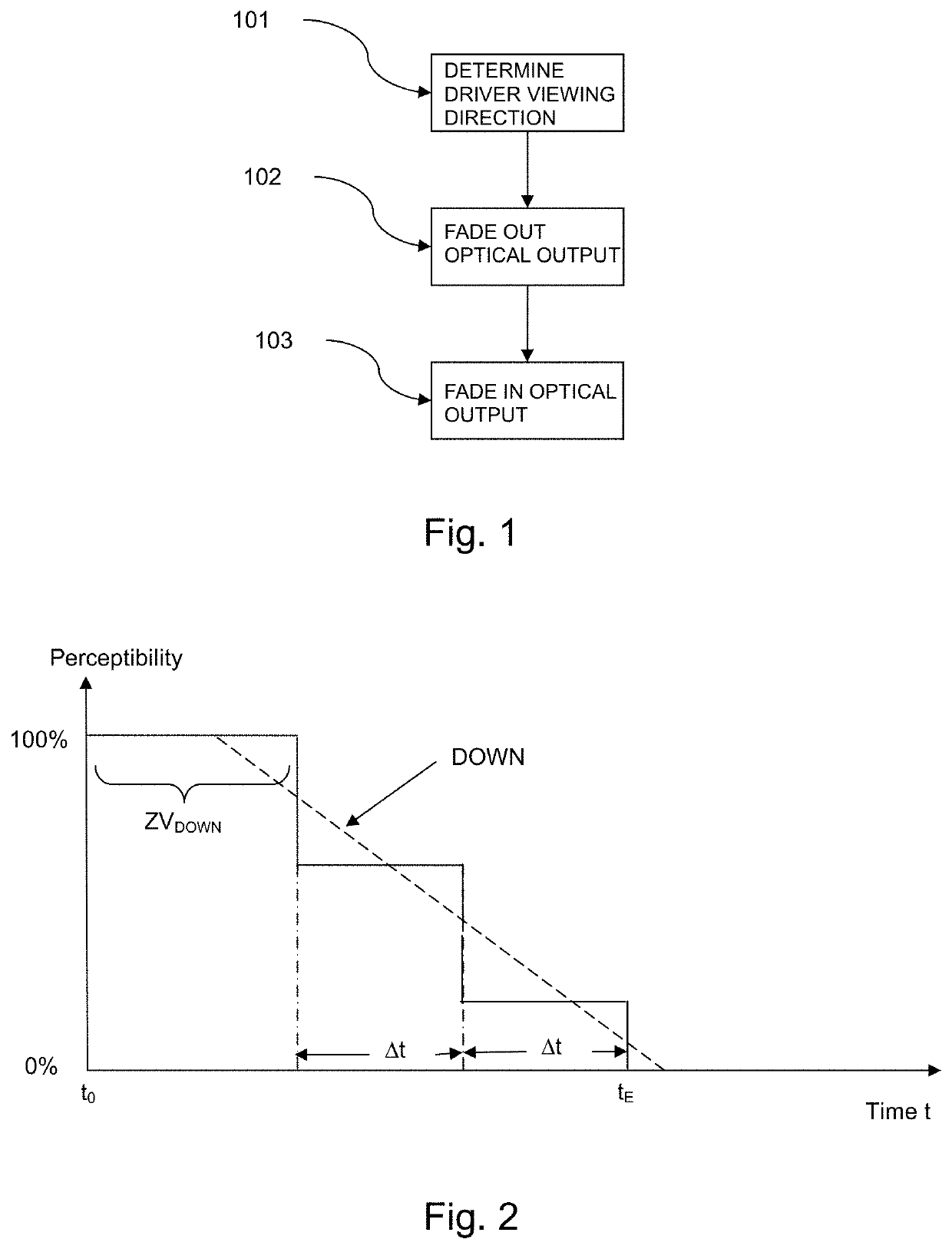
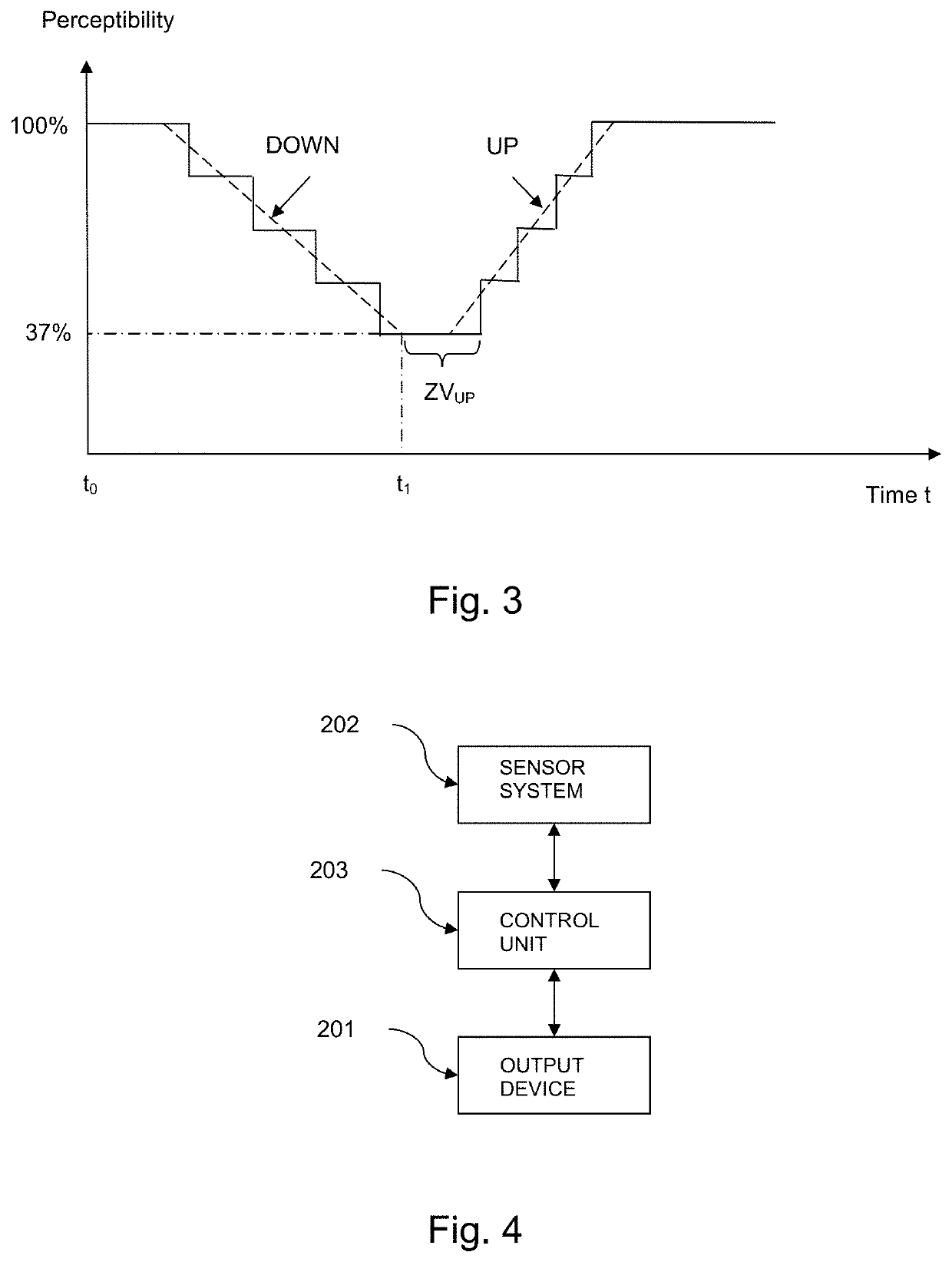
[0065]FIG. 1 shows a highly schematized sequence of a method according to the invention for influencing an optical output of image data on an output device in a vehicle, with the following steps. In a step 101, a viewing direction of a driver of the vehicle is determined in the vehicle. In a step 102, if the determined viewing direction is directed to the output device, the optical output of the image data is faded out at an average fading out rate DOWN, wherein the fading out rate DOWN defines a temporal decrease in the optical perceptibility of the output image data by a human. In a step 103, if the determined viewing direction is directed towards the output device and is directed away from the output device, the optical output of the image data is faded in at an average fading in rate UP, wherein the fading in rate UP describes a temporal increase in the optical perceptibility of the output image data by a human. In particular, UP>DOWN applies.

[0066]FIG. 2 shows an example of a c...


PUM


Abstract

A method and a system for influencing an optical output of image data on an output device in a vehicle. A viewing direction of a driver of the vehicle is determined. If the determined viewing direction is directed to the output device, the optical output of the image data is faded down with an average fading out rate DOWN. The fading out rate DOWN defines a temporal decrease in the optical perceptibility of the output image data by a human. If the determined viewing direction is directed towards the output device and is directed away from the output device, the optical output of the image data is faded up with an average fading in rate UP. The fading in rate UP defines a temporal increase of the optical perceptibility of the output image data by a human.

Description

BACKGROUND AND SUMMARY OF THE INVENTION[0001]Exemplary embodiments of the invention relate to a method and device for influencing an optical output of image data on an optical output device in a vehicle, in particular in a motor vehicle, and to a vehicle having such a device.[0002]The reproduction of image data, in particular moving images, such as: videos, animations, clips etc. on optical output devices that can be viewed by the driver of the vehicle, is not permitted in numerous countries for safety reasons during operation of the vehicle due to the high distraction potential for the respective driver.[0003]In order to nevertheless enable the reproduction of image data by means of such an optical output device, for example for a passenger sitting next to the driver, a method and a device for influencing the attention of a driver of a motor vehicle is known, for example, from the printed publication DE 10 2011 084 887 A1, which comprises a system having an optical output device.[0...

Claims


Application Information

Patent Timeline
Patent Type & Authority Applications(United States)
IPC IPC(8): G09G3/00G06V40/18G06F3/01B60K35/00
CPCG09G3/002G06V40/18G06F3/013B60K35/00G09G2320/0626B60K2370/21G09G2340/14G09G2380/10B60K2370/33B60K2370/149B60K2370/1529G09G2354/00G06F3/04847B60K2370/1868B60K2370/1876
Inventor SCHMID, THOMASENZMANN, HOLGERPATZELT, CHRISTIANGULDE, GERDHALLIER, NINA
Owner DAIMLER AG
Why Eureka
Try Eureka