Atomization device
a technology of atomization device and saline solution, which is applied in the direction of medical devices, inhalators, medical applicators, etc., can solve the problems of inconvenient us
- Summary
- Abstract
- Description
- Claims
- Application Information
AI Technical Summary
Benefits of technology
Problems solved by technology
Method used
Image
Examples
first embodiment
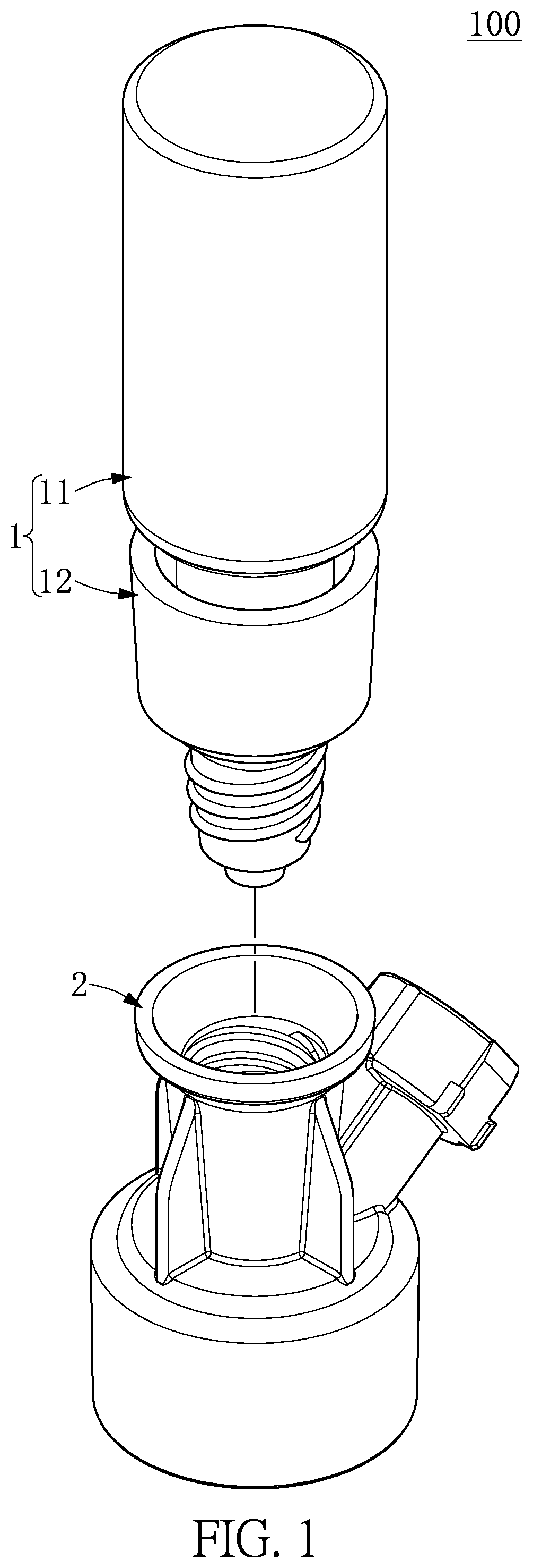
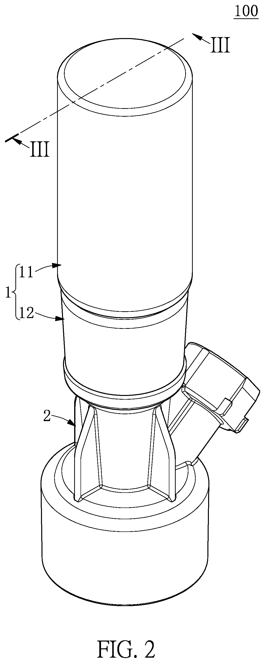
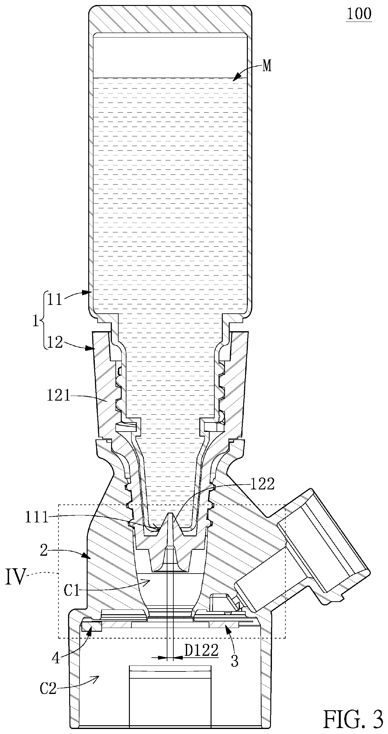
[0043]Referring to FIG. 1 to FIG. 4, a first embodiment of the present disclosure provides an atomization device 100. The atomization device 100 of the present embodiment includes a disposable liquid supply module 1, a carrier 2 detachably assembled to the disposable liquid supply module 1, and an atomizing module 3 that is assembled to at least one of the disposable liquid supply module 1 and the carrier 2. In the present embodiment, the atomizing module 3 is exemplified as being only assembled to the carrier 2.
[0044]The disposable liquid supply module 1 includes a liquid storing member 11 and an opener 12 that is disposed on the liquid storing member 11, and the opener 12 is configured to form an opening 111 on the liquid storing member 11, but the present disclosure is not limited thereto. For example, in other embodiments of the present disclosure not shown in the drawings, the liquid storing member 11 and the opener 12 can be two components that are separate from each other; or...
second embodiment
[0055]Referring to FIG. 5 to FIG. 8, a second embodiment of the present disclosure provides an atomization device 100, which includes a disposable liquid supply module 1, a carrier 2 detachably assembled to the disposable liquid supply module 1, and an atomizing module 3 that is assembled to at least one of the disposable liquid supply module 1 and the carrier 2. In the present embodiment, the atomizing module 3 is exemplified as being assembled to the disposable liquid supply module 1 and the carrier 2.
[0056]The disposable liquid supply module 1 includes a liquid storing member 11, an opener 12 that is configured to form an opening 111 on the liquid storing member 11, and a container 13 that is spaced apart from the liquid storing member 11 and the opener 12. Specifically, the liquid storing member 11 stores liquid M (e.g., a liquid medicine or a skincare liquid) therein, and the type of the liquid M can be adjusted or changed according to design requirements. It should be noted th...
third embodiment
[0069]Referring to FIG. 9 to FIG. 15, a third embodiment of the present disclosure provides an atomization device 100. As shown in FIG. 9 to FIG. 11, the atomization device 100 includes a disposable liquid supply module 1, a carrier 2 detachably assembled to the disposable liquid supply module 1, and an atomizing module 3 that is assembled to at least one of the disposable liquid supply module 1 and the carrier 2. In the present embodiment, the atomizing module 3 is exemplified as being assembled to the disposable liquid supply module 1 and the carrier 2.
[0070]It should be noted that the carrier 2 and the atomizing module 3 of the present embodiment are similar to those of the second embodiment. Therefore, for the features of the carrier 2 and the atomizing module 3 of the present embodiment, reference can also be made to FIG. 5 to FIG. 8 of the second embodiment.
[0071]The disposable liquid supply module 1 includes a liquid storing member 11 and an opener 12 that is configured to fo...
PUM
 Abstract
Description
Claims
Application Information
 - R&D
- Intellectual Property
- Life Sciences
- Materials
- Tech Scout
- Unparalleled Data Quality
- Higher Quality Content
- 60% Fewer Hallucinations
Browse by: Latest US Patents, China's latest patents, Technical Efficacy Thesaurus, Application Domain, Technology Topic, Popular Technical Reports.
© 2025 PatSnap. All rights reserved.Legal|Privacy policy|Modern Slavery Act Transparency Statement|Sitemap|About US| Contact US: help@patsnap.com


