Lighting touchpad
a touchpad and light technology, applied in the field of touch panels, can solve the problems of affecting the touch control effect of the lateral portions of the conventional lighting touchpad, and achieve the effect of improving the light control
- Summary
- Abstract
- Description
- Claims
- Application Information
AI Technical Summary
Benefits of technology
Problems solved by technology
Method used
Image
Examples
first embodiment
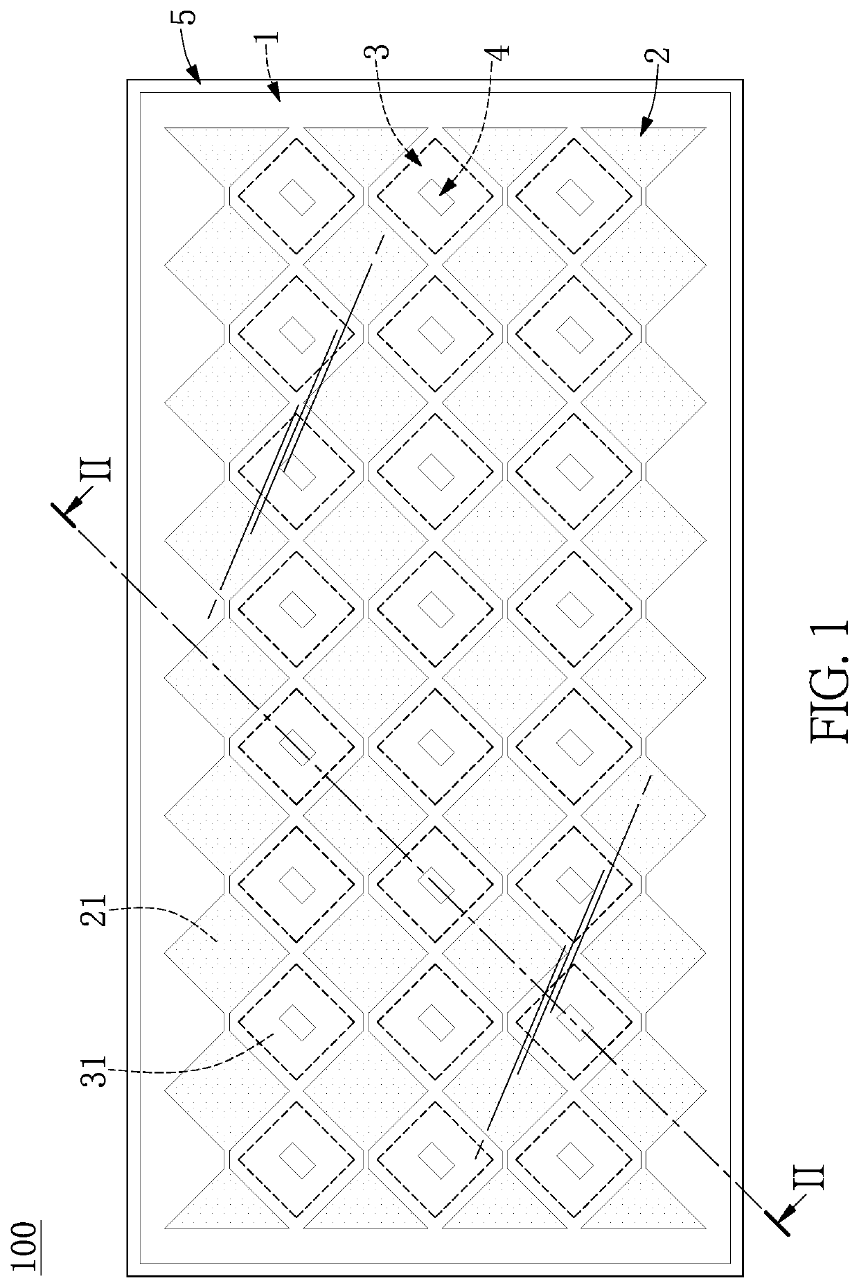
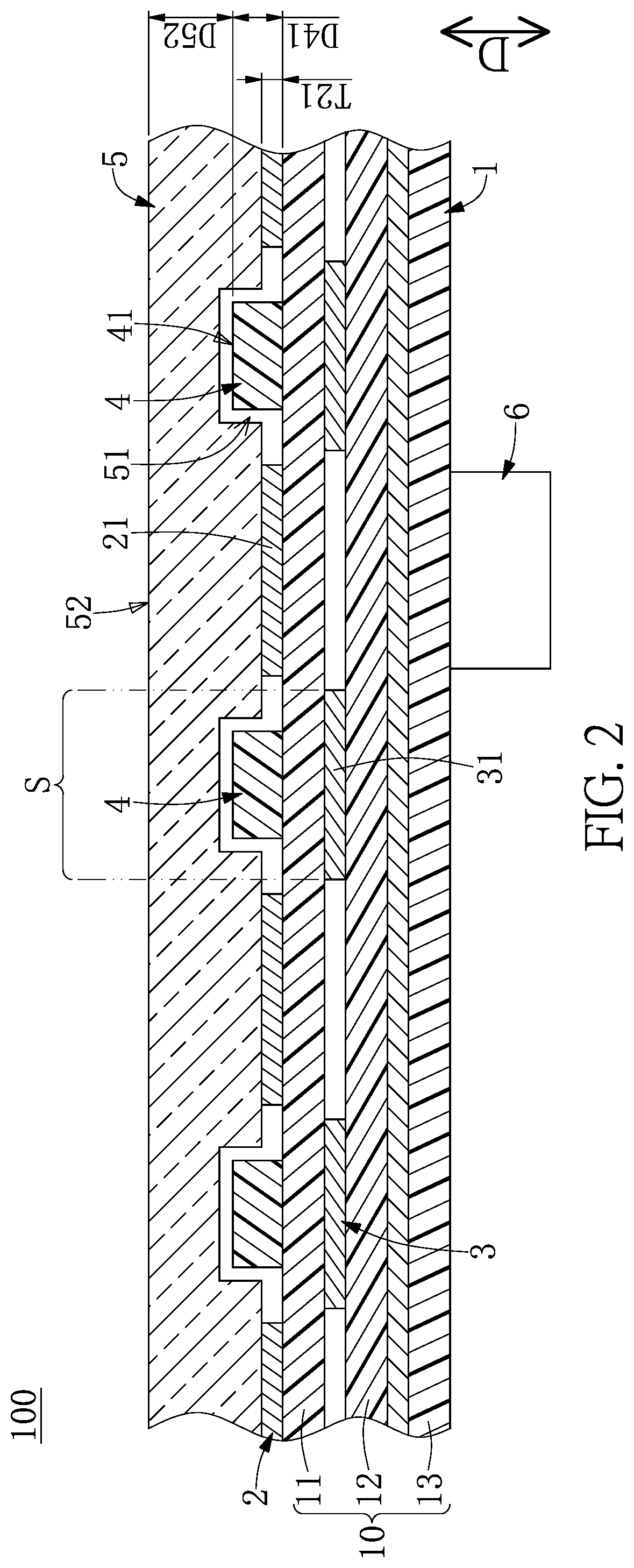
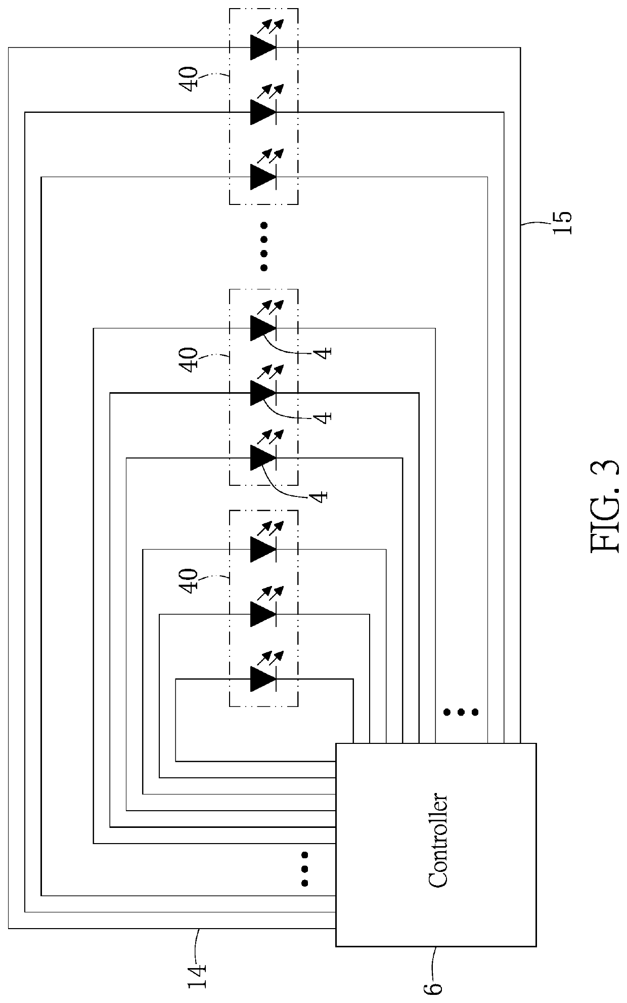
[0040]Referring to FIG. 1 to FIG. 4, a first embodiment of the present disclosure provides a lighting touchpad 100. As shown in FIG. 1 and FIG. 2, the lighting touchpad 100 includes a substrate module 1, a sensing electrode layer 2, a driving electrode layer 3, a plurality of light emitting diode (LED) chips 4, a protective layer 5, and a controller 6. The sensing electrode layer 2, the driving electrode layer 3, the LED dies 4, and the controller 6 are mounted on the substrate module 1, and the protective layer 5 covers (or is disposed above) the sensing electrode layer 2 and the LED dies 4.
[0041]It should be noted that the lighting touchpad 100 in the present embodiment includes the above components, but the present disclosure is not limited thereto. For example, in other embodiments of the present disclosure not shown in the drawings, the protective layer 5 of the lighting touchpad 100 can be omitted or can be replaced by other components. The following description describes the ...
second embodiment
[0058]Referring to FIG. 5 and FIG. 6, a second embodiment of the present disclosure is similar to the first embodiment of the present disclosure. For the sake of brevity, descriptions of the same components in the first and second embodiments of the present disclosure will be omitted herein, and the following description only discloses different features between the first and second embodiments.
[0059]In the present embodiment, the sensing electrodes 21, the driving electrodes 31, and the LED dies 4 are jointly disposed on one of the substrates 10 (e.g., the first substrate 11) of the substrate module 1, and the protective layer 5 covers the sensing electrodes 21, the driving electrodes 31, and the LED dies 4. In other words, the substrate module 1 in the present embodiment can be provided without the second substrate 12 disclosed in the first embodiment.
[0060]Specifically, each of the driving electrodes 31 is formed to surround one of a plurality of distribution regions S1. In the p...
third embodiment
[0064]Referring to FIG. 7, a third embodiment of the present disclosure is similar to the second embodiment of the present disclosure. For the sake of brevity, descriptions of the same components in the second and third embodiments of the present disclosure will be omitted herein, and the following description only discloses different features between the second and third embodiments.
[0065]In the present embodiment, the driving electrodes 31 and the sensing electrodes 21 are jointly disposed on one of the substrates 10 of the substrate module 1 (e.g., the first substrate 11), and the LED dies 4 are disposed on another one of the substrates 10 of the substrate module 1 (e.g., the second substrate 12). In other words, the substrate module 1 in the present embodiment can include the second substrate 12 disclosed in the first embodiment.
[0066]Specifically, the protective layer 5 covers (or is disposed on) the sensing electrodes 21 and the driving electrodes 31. The first substrate 11 ha...
PUM
 Abstract
Description
Claims
Application Information
 - R&D
- Intellectual Property
- Life Sciences
- Materials
- Tech Scout
- Unparalleled Data Quality
- Higher Quality Content
- 60% Fewer Hallucinations
Browse by: Latest US Patents, China's latest patents, Technical Efficacy Thesaurus, Application Domain, Technology Topic, Popular Technical Reports.
© 2025 PatSnap. All rights reserved.Legal|Privacy policy|Modern Slavery Act Transparency Statement|Sitemap|About US| Contact US: help@patsnap.com


